Image forming apparatus, transfer current control method and storage medium

a technology of image forming apparatus and transfer current, which is applied in the direction of electrographic process apparatus, instruments, optics, etc., can solve the problems of inconvenient use and excessive standby time, and achieve the effects of suppressing the degradation of the image quality of the output image, effective control, and effective suppression of the re-transfer of toner

Active Publication Date: 2016-04-26
SHARP KK
View PDF6 Cites 0 Cited by
  • Summary
  • Abstract
  • Description
  • Claims
  • Application Information

AI Technical Summary

Benefits of technology

[0009]It is another object of the present invention to provide an image forming apparatus, transfer current control method and storage medium, capable of preventing a poor image due to a contact trace that occurs on the transfer belt without extending preliminary operation time.
[0030]According to the seventh invention and the eighth invention, like the first invention, it is possible to prevent, without extending a preliminary operation time, a poor image due to a contact trace that is formed on the transfer belt.

Problems solved by technology

However, in the technology of Patent Literature 1, since the preliminary operation time is extended in order to recover the contact trace of the transfer belt, excessive standby time becomes needed and inconvenient to a user.

Method used


Image

  • Image forming apparatus, transfer current control method and storage medium
  • Image forming apparatus, transfer current control method and storage medium
  • Image forming apparatus, transfer current control method and storage medium

Examples


first embodiment

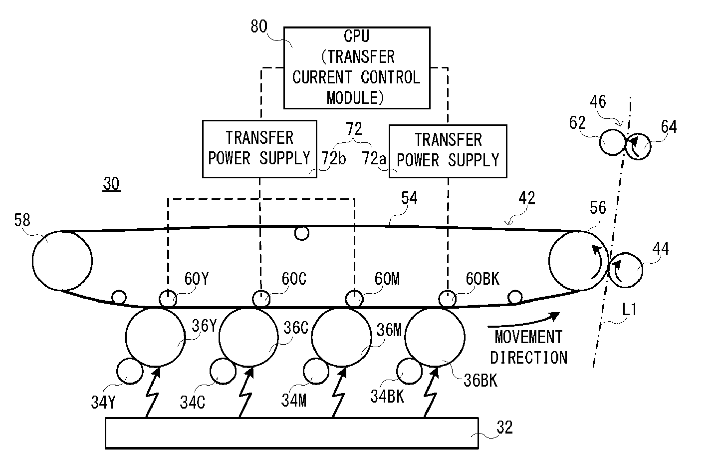
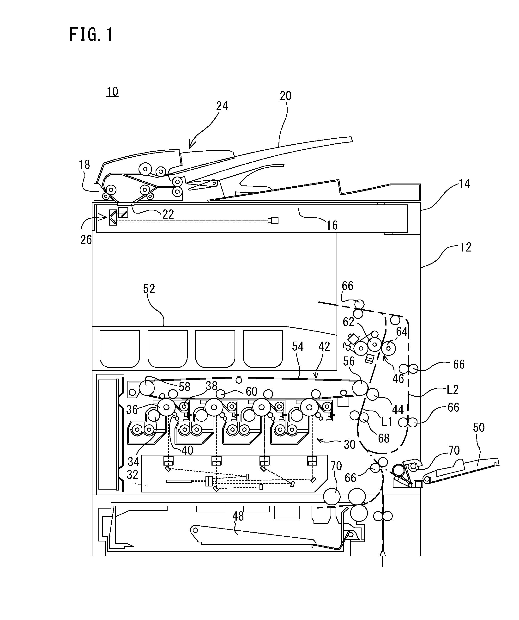
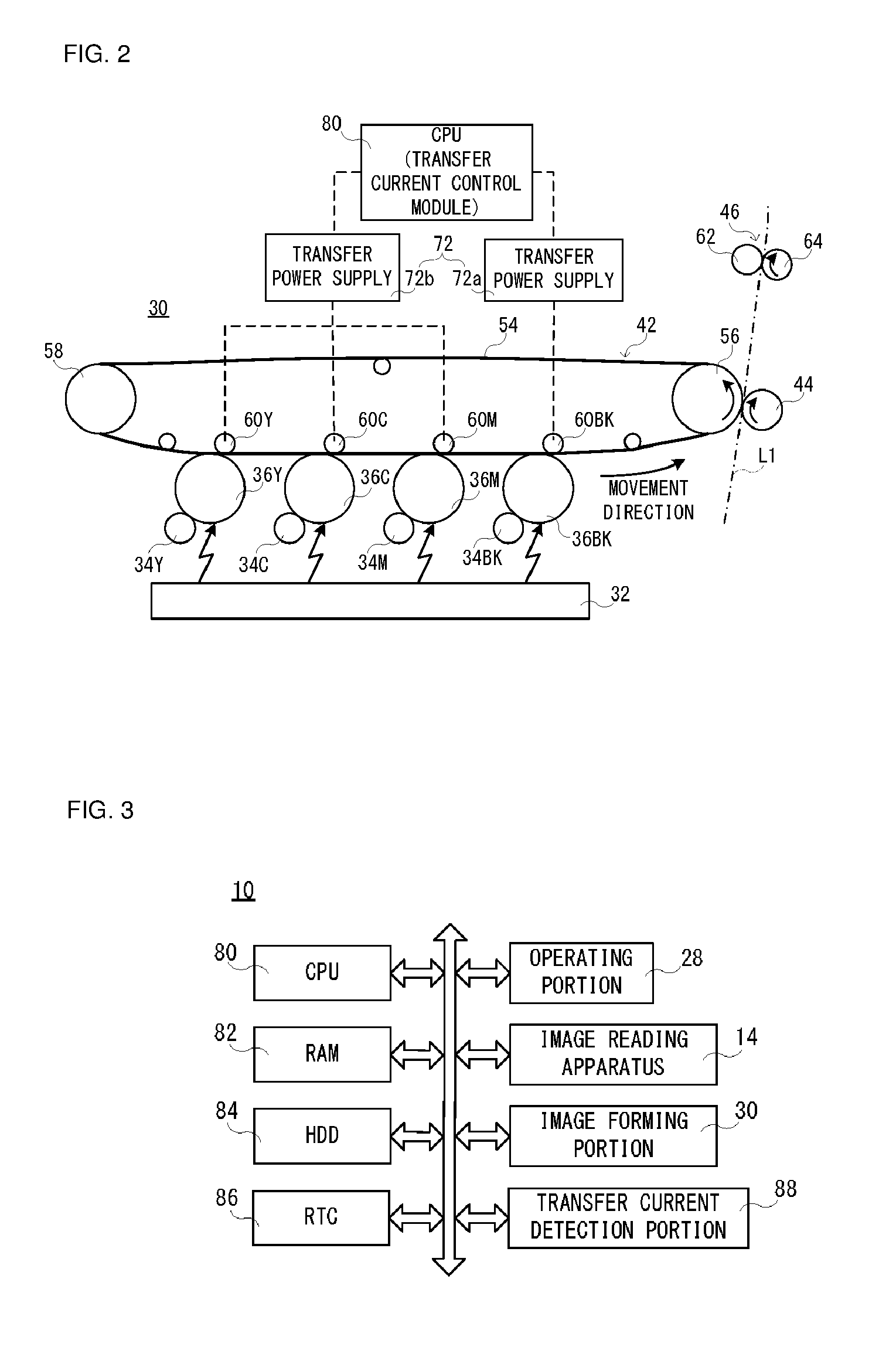
[0040]With reference to FIG. 1, an image forming apparatus 10 that is an embodiment according to the present invention is a multifunction peripheral (MFP) that has a copy function, a printer function, a scanner function, a facsimile function, etc., and operates in a color printing mode or a monochrome printing mode to form a multicolor or monochromatic image on a paper (recording medium). As details will be described later, the image forming apparatus 10 comprises an image forming portion 30 of an intermediate transfer system, and transfers a toner image formed on a photoreceptor drum 36 to a paper using an intermediate transfer belt (primary transfer belt) 54 that is stretched over a plurality of rollers 56 and 58 to be circumferentially moved, etc.

[0041]First, basic structure of the image forming apparatus 10 will be described roughly. As shown in FIG. 1 and FIG. 2, the image forming apparatus 10 comprises a main body 12 that is provided with an image forming portion 30, etc., and...

second embodiment

[0110]Next, with reference to FIG. 6, an image forming apparatus 10 that is the second embodiment according to the present invention will be described. This second embodiment is different from the above-described first embodiment in a point that a reduction range of the transfer current to be supplied to the intermediate transfer roller 60BK is made larger as the non-use period showing a time period that the apparatus power supply of the image forming apparatus 10 is in an off state becomes longer. Since other portions are the same as those of the above-described first embodiment, a duplicate description is omitted or simplified, and an example of entire processing of an image forming operation the CPU 80 performs will be described here using a flowchart.

[0111]As shown in FIG. 6, when the apparatus power supply of the image forming apparatus 10 is turned on, the CPU 80 performs preliminary operation processing in a step S21. In a next step S23, information of the non-use period is a...

third embodiment

[0127]Subsequently, with reference to FIG. 7, an image forming apparatus 10 that is the third embodiment according to the present invention will be described. This third embodiment is different from the above-described first embodiment and the second embodiment, in a point that a time period that until a current value being changed of the transfer current is returned to the standard value is lengthened as the non-use period that shows the time period that the apparatus power supply of the image forming apparatus 10 is in an off state becomes long. Since other portions are the same as those of the above-described first embodiment and second embodiment, a duplicate description is omitted or simplified, and an example of entire processing of an image forming operation the CPU 80 performs will be described here using a flowchart.

[0128]As shown in FIG. 7, when the apparatus power supply of the image forming apparatus 10 is turned on, the CPU 80 performs preliminary operation processing i...


PUM


Abstract

An image forming apparatus includes a transfer belt that is stretched over a plurality of rollers to be circumferentially moved, a transfer roller, a transfer power supply, etc., and transfers a toner image formed on an image carrying member to a recording medium using the transfer belt. The image forming apparatus includes a transfer current control unit that measures a use situation of the transfer belt and controls a transfer current to be supplied to the transfer roller based on the use situation. Since re-transfer of a toner is prevented by controlling the transfer current that flows into the transfer roller based on the use situation of the transfer belt, it is possible to prevent, without extending preliminary operation time of the transfer belt, a poor image due to a contact trace that occurs on the transfer belt.

Description

CROSS REFERENCE OF RELATED APPLICATION[0001]The disclosure of Japanese patent application No. 2014-089447 filed on Apr. 23, 2014 is incorporated by reference.BACKGROUND OF THE INVENTION[0002]1. Field of the Invention[0003]The present invention relates to an image forming apparatus, a transfer current control method and a storage medium, and more specifically, an image forming apparatus that a toner image formed on an image carrying member is transferred to a recording medium using a transfer belt that is stretched over a plurality of rollers to be circumferentially moved, a transfer current control method and a storage medium.[0004]2. Description of the Related Art[0005]An example of the conventional image forming apparatus is disclosed in Japanese patent application laying-open No. 2005-122019 [G03G 15 / 16, G03G 15 / 02, G03G 15 / 20, G03G 21 / 14] (Patent Literature 1) laid-open on May 12, 2005. The image forming apparatus of Patent Literature 1 comprises a transfer belt (movable member)...

Claims


Application Information

Patent Timeline
Patent Type & Authority Patents(United States)
IPC IPC(8): G03G15/16G03G15/00
CPCG03G15/16G03G15/1605G03G15/80G03G15/1645G03G15/1675G03G2215/0132
Inventor TERAMOTO, YUDAI
Owner SHARP KK
Why Eureka
Try Eureka