Image forming apparatus, transfer current control method and storage medium
a technology of image forming apparatus and transfer current, which is applied in the direction of electrographic process apparatus, instruments, optics, etc., can solve the problems of inconvenient use and excessive standby time, and achieve the effects of suppressing the degradation of the image quality of the output image, effective control, and effective suppression of the re-transfer of toner
- Summary
- Abstract
- Description
- Claims
- Application Information
AI Technical Summary
Benefits of technology
Problems solved by technology
Method used
Image
Examples
first embodiment
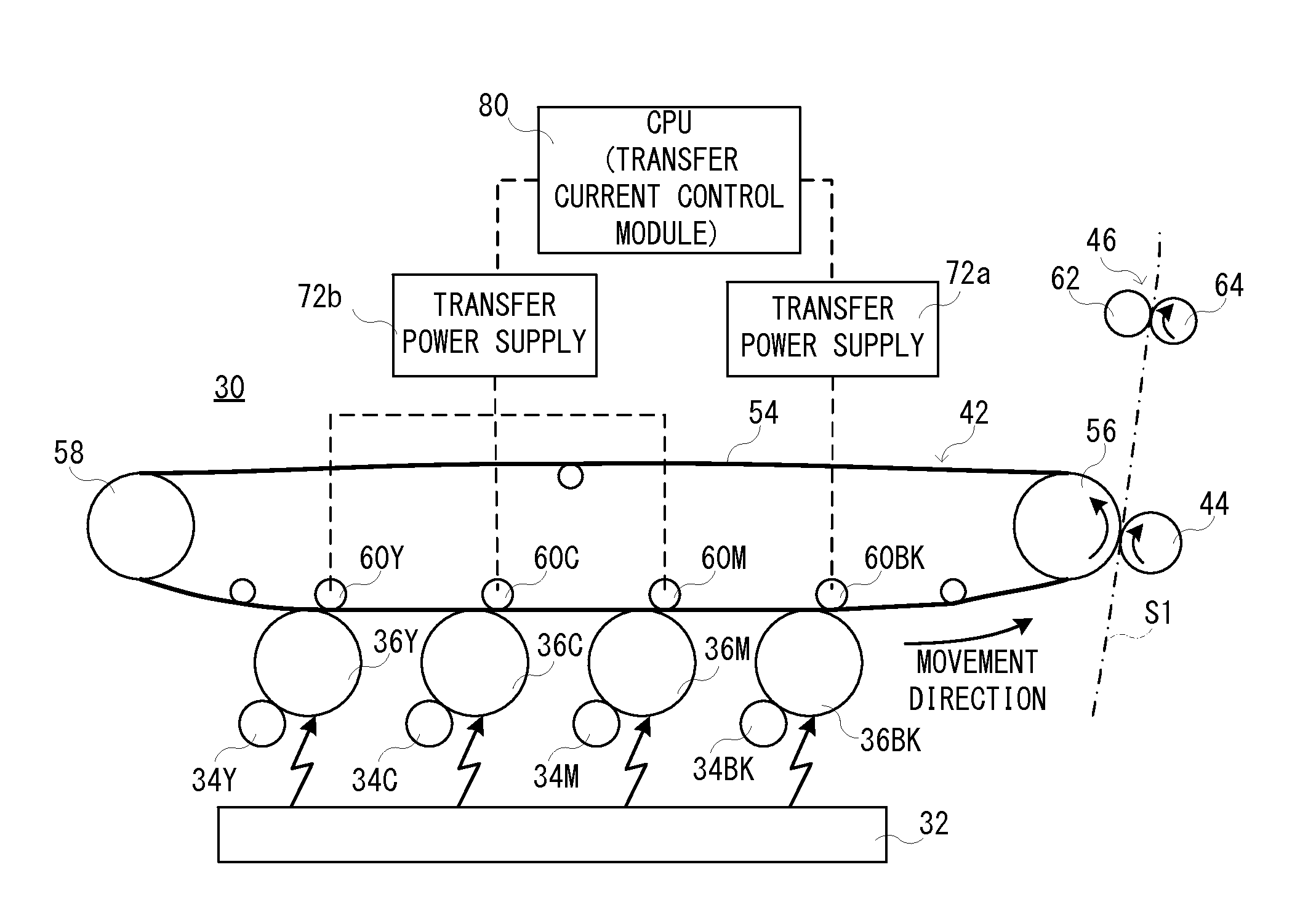
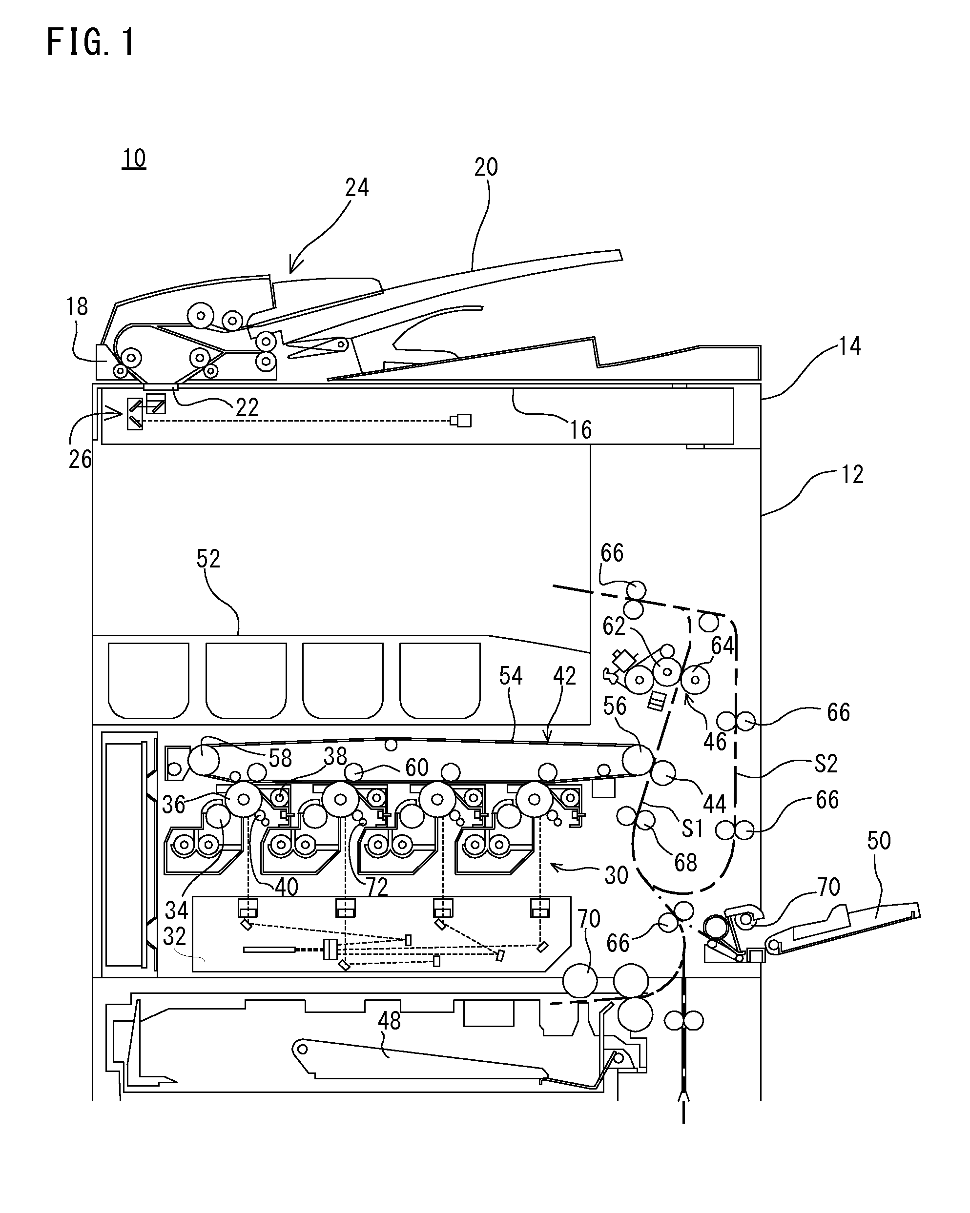
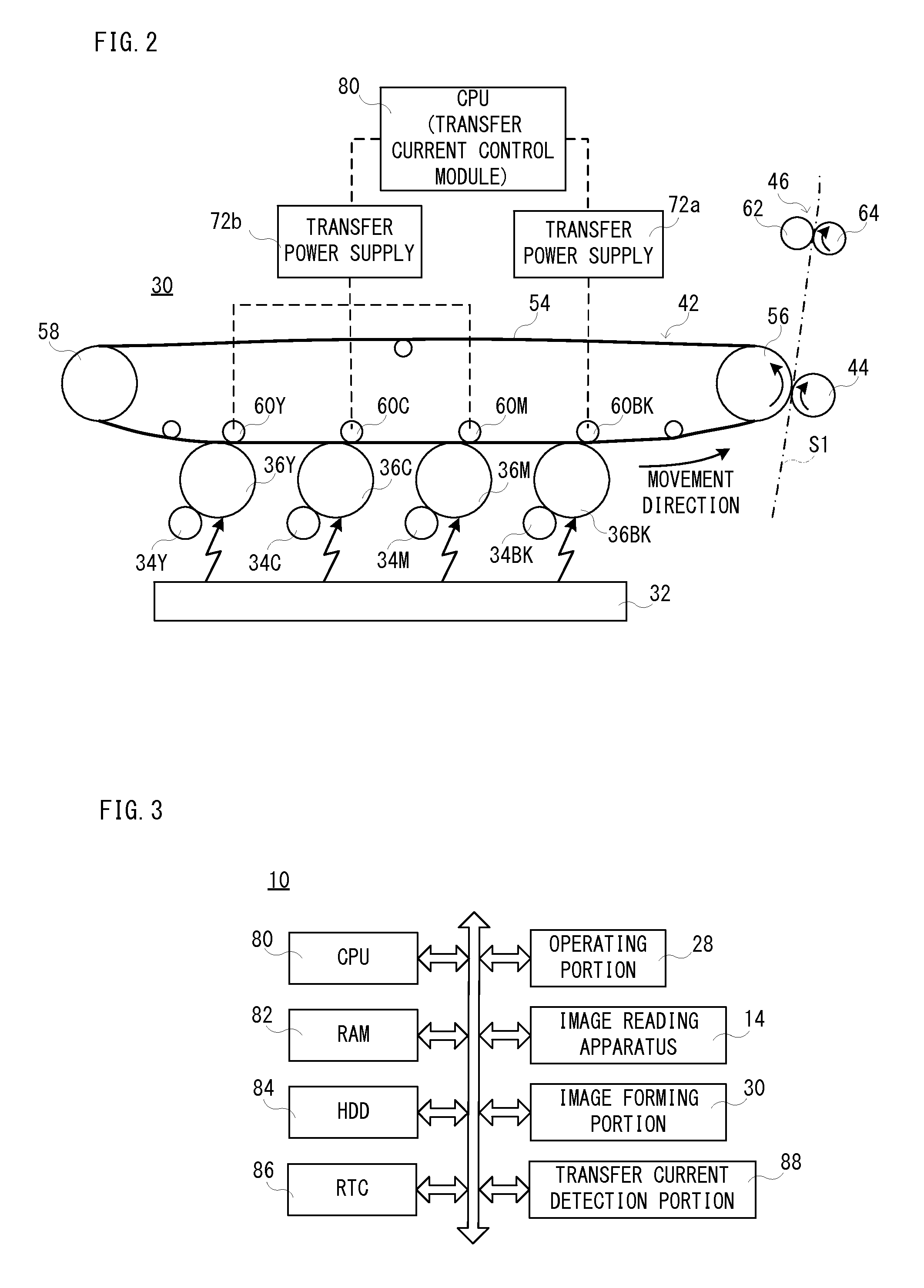
[0040]With reference to FIG. 1, an image forming apparatus 10 that is an embodiment according to the present invention is a multifunction peripheral (MFP) that has a copy function, a printer function, a scanner function, a facsimile function, etc., and operates in a color printing mode or a monochrome printing mode to form a multicolor or monochromatic image on a paper (recording medium). As details will be described later, the image forming apparatus 10 comprises an image forming portion 30 of an intermediate transfer system, and transfers a toner image formed on a photoreceptor drum 36 to a paper using an intermediate transfer belt (primary transfer belt) 54 that is stretched over a plurality of rollers 56 and 58 to be circumferentially moved, etc.
[0041]First, basic structure of the image forming apparatus10 will be described roughly. As shown in FIG. 1 and FIG. 2, the image forming apparatus 10 comprises a main body 12 that is provided with an image forming portion 30, etc., and ...
second embodiment
[0110]Next, with reference to FIG. 6, an image forming apparatus 10 that is the second embodiment according to the present invention will be described. This second embodiment is different from the above-described first embodiment in a point that a reduction range of the transfer current to be supplied to the intermediate transfer roller 60BK is made larger as the non-use period showing a time period that the apparatus power supply of the image forming apparatus 10 is in an off state becomes longer. Since other portions are the same as those of the above-described first embodiment, a duplicate description is omitted or simplified, and an example of entire processing of an image forming operation the CPU 80 performs will be described here using a flowchart.
[0111]As shown in FIG. 6, when the apparatus power supply of the image forming apparatus 10 is turned on, the CPU 80 performs preliminary operation processing in a step S21. In a next step S23, information of the non-use period is a...
third embodiment
[0127]Subsequently, with reference to FIG. 7, an image forming apparatus 10 that is the third embodiment according to the present invention will be described. This third embodiment is different from the above-described first embodiment and the second embodiment, in a point that a time period that until a current value being changed of the transfer current is returned to the standard value is lengthened as the non-use period that shows the time period that the apparatus power supply of the image forming apparatus 10 is in an off state becomes long. Since other portions are the same as those of the above-described first embodiment and second embodiment, a duplicate description is omitted or simplified, and an example of entire processing of an image forming operation the CPU 80 performs will be described here using a flowchart.
[0128]As shown in FIG. 7, when the apparatus power supply of the image forming apparatus 10 is turned on, the CPU 80 performs preliminary operation processing i...
PUM
 Abstract
Description
Claims
Application Information
 - R&D
- Intellectual Property
- Life Sciences
- Materials
- Tech Scout
- Unparalleled Data Quality
- Higher Quality Content
- 60% Fewer Hallucinations
Browse by: Latest US Patents, China's latest patents, Technical Efficacy Thesaurus, Application Domain, Technology Topic, Popular Technical Reports.
© 2025 PatSnap. All rights reserved.Legal|Privacy policy|Modern Slavery Act Transparency Statement|Sitemap|About US| Contact US: help@patsnap.com


