
Liquid crystal display

a liquid crystal display and display technology, applied in non-linear optics, instruments, optics, etc., can solve problems such as serious problems such as the deterioration of image quality due to vertical bouncing

Inactive Publication Date: 2006-12-21
SAMSUNG ELECTRONICS CO LTD
View PDF9 Cites 2 Cited by
  • Summary
  • Abstract
  • Description
  • Claims
  • Application Information

AI Technical Summary

Benefits of technology

[0009] An LCD according to an embodiment of the present invention prevents poor images of an LCD.
[0010] An LCD according to an embodiment of the present invention establishes the relation of ε (permittivity)·ρ (resistivity) between a liquid crystal layer, an aligning layer or an overcoat for preventing poor images so that the bouncing dose not appear.

Problems solved by technology

In such an LCD, deterioration of image quality due to vertical bouncing becomes a serious problem.

Method used


Image

  • Liquid crystal display
  • Liquid crystal display
  • Liquid crystal display

Examples


Embodiment Construction

[0032] Now, the present invention will be described in detail with reference to the accompanying drawings.

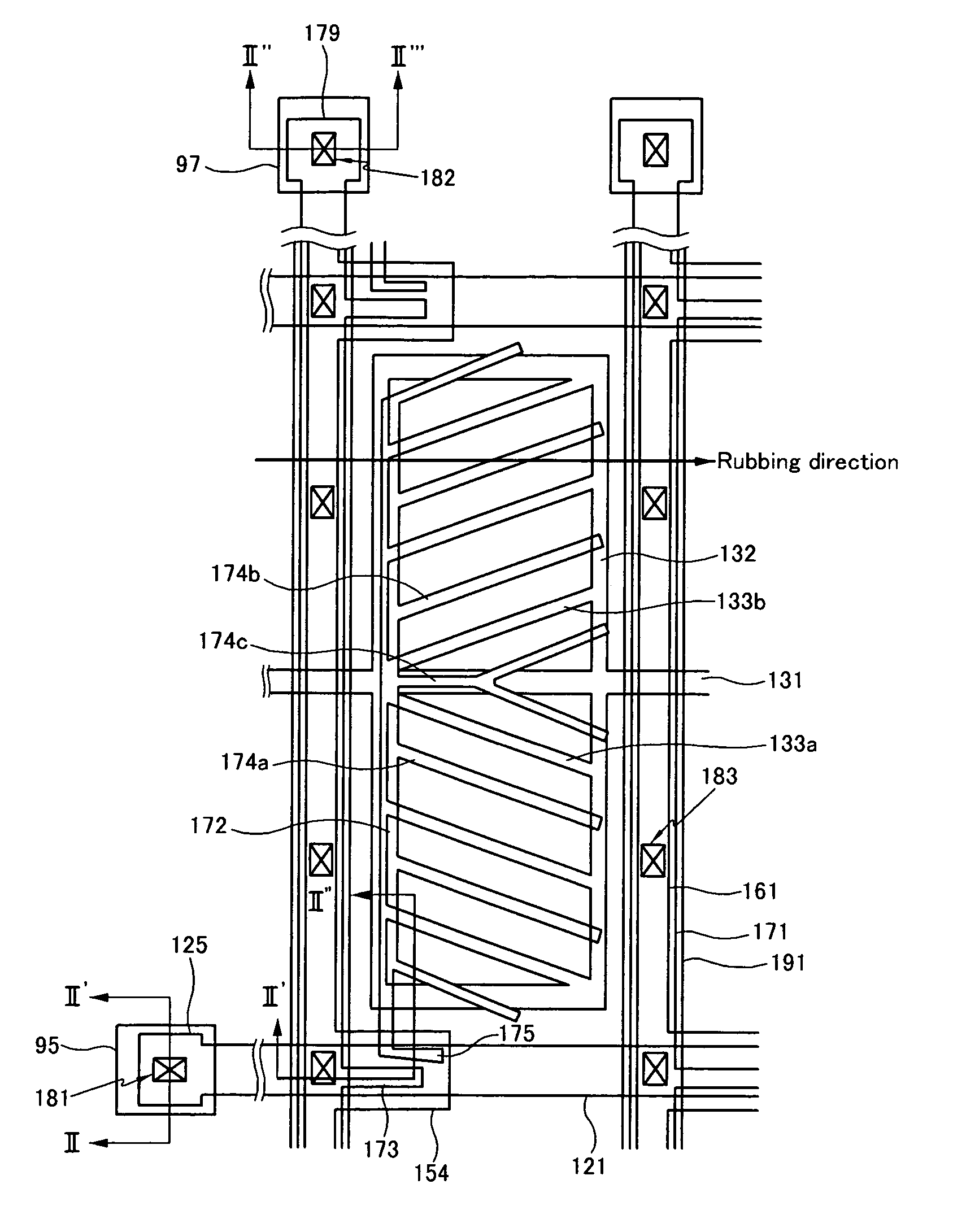
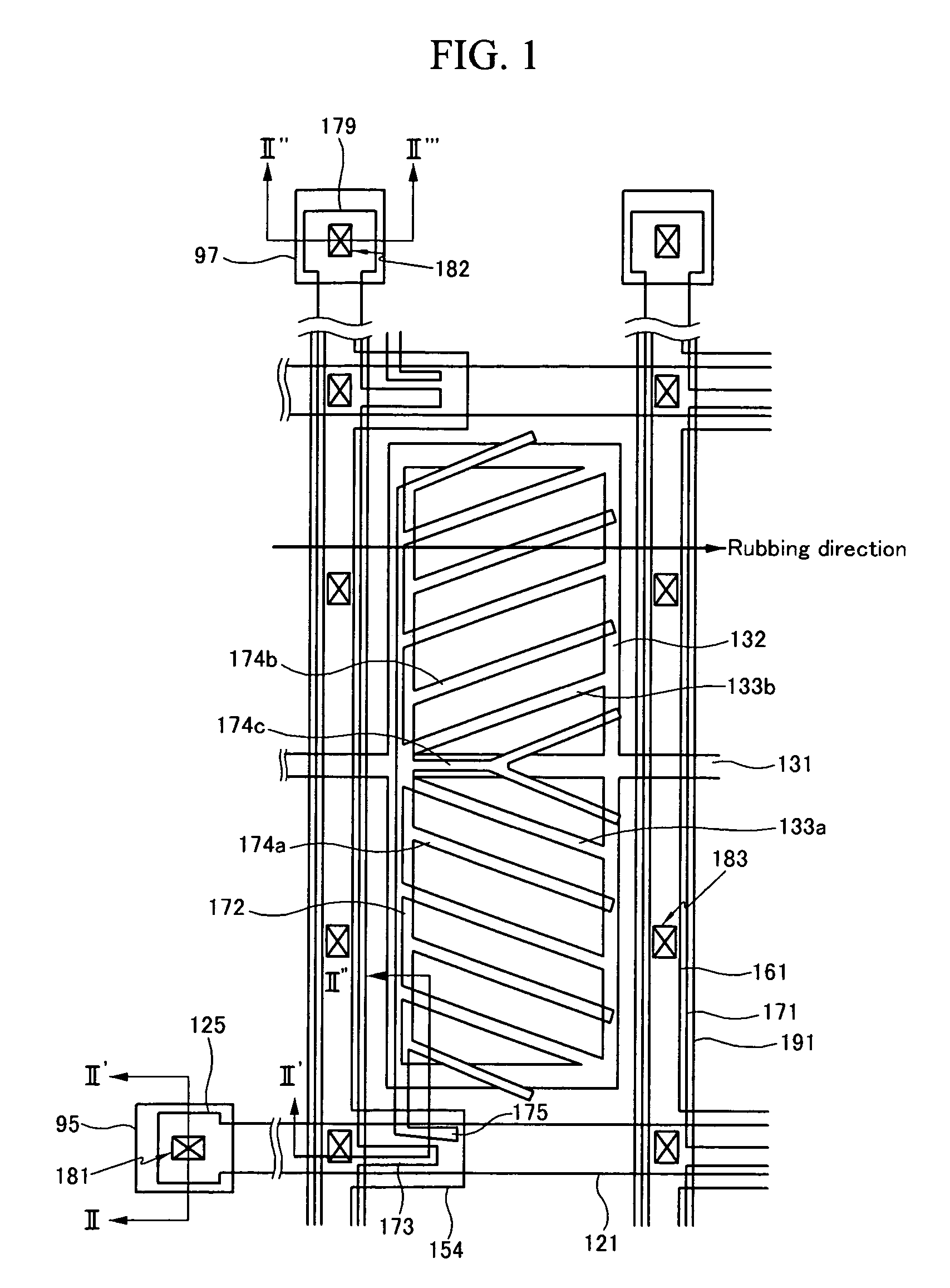
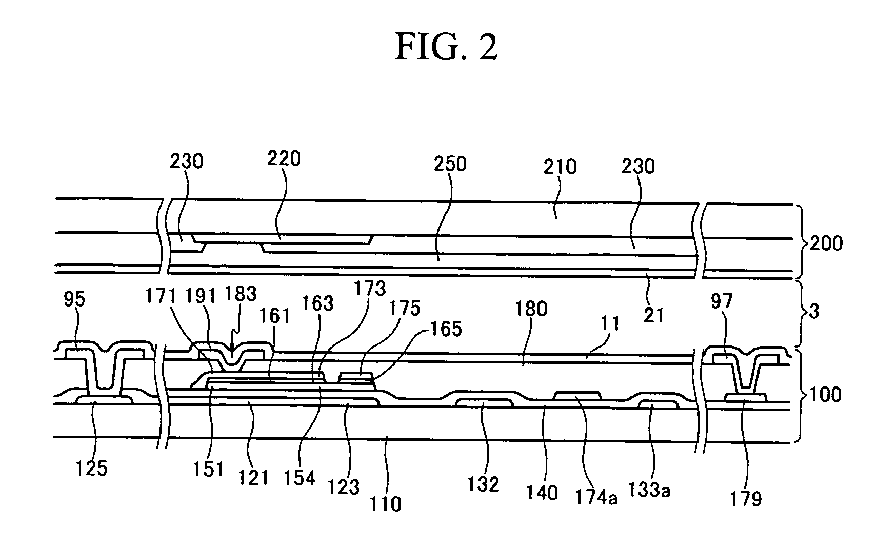
[0033]FIG. 1 is a layout view of an exemplary LCD according to an embodiment of the present invention, and FIG. 2 is a sectional view of the LCD shown in FIG. 1 taken along the lines II-II′, II′-II″, and II″-II′″.

[0034] An exemplary LCD according to an embodiment of the present invention includes a thin film transistor array panel 100, a color filter array panel 200, and a liquid crystal layer 3 interposed between the thin film transistor array panel 100 and the color filter array panel 200.

[0035] Now, the thin film transistor array panel 100 will be described in detail.

[0036] A plurality of gate lines 121 for transmitting gate signals and a plurality of common electrode lines 131 for transmitting a common voltage are formed on an insulating substrate 110.

[0037] Each gate line 121 extends substantially in a transverse direction and a plurality of portions of each gate line ...


PUM


Abstract

The present invention relates to a liquid crystal display. The relation of ε (permittivity)·ρ (resistivity) between a liquid crystal layer, an aligning layer or an overcoat for preventing poor images is established. An LCD according to the present invention includes a first panel including a plurality of devices thereon and an aligning layer formed on the entire surface thereof, a second panel opposite to the first panel and including an overcoat and an aligning layer sequentially formed on the entire surface thereof, and a liquid crystal layer interposed between the first panel and the second panel. It is preferable that the aligning layer, the liquid crystal layer and the overcoat satisfy the relation ρɛlc+alρɛoc≻102.An LCD according to another embodiment includes a first panel including a plurality of devices thereon and an aligning layer formed on the entire surface thereof, a second panel opposite to the first panel and including an overcoat and an aligning layer sequentially formed on the entire surface thereof, and a liquid crystal layer interposed between the first panel and the second panel. It is preferable that the liquid crystal and the overcoat satisfy the relation RClcRCoc≻103.

Description

CROSS-REFERENCES TO RELATED APPLICATIONS [0001] This application is a Continuation-In-Part of U.S. application Ser. No. 11 / 180,654, filed on Jul. 14, 2005, which is a Continuation of U.S. patent application Ser. No. 10 / 398,480, filed on May 22, 2003, now U.S. Pat. No. 6,927,827, which claims priority to Korean Patent Application No. 2001-47488, filed on Aug. 7, 2001, the disclosures of which are all incorporated herein in their entireties by reference.BACKGROUND OF THE INVENTION [0002] (a) Field of the Invention [0003] The present invention relates to a liquid crystal display, and in particular to a coplanar electrode (“CE”) type liquid crystal display and a manufacturing method thereof. [0004] (b) Description of the Related Art [0005] A coplanar electrode (“CE”) type liquid crystal display (“LCD”) includes a plurality of pixel electrodes and a plurality of common electrodes provided on one panel. The CE type LCD drives liquid crystal molecules using horizontal electric field nearly...

Claims


Application Information

Patent Timeline
IPC IPC(8): G02F1/1343
CPCG02F1/1337G02F1/133519
Inventor JUNG, CHEOL-SOOHAN, KEON-KOOKJOO, YOUNG-KUILKO, JI-YONGCHO, YOUNG-HWANMIN, KYOUNG-WOO
Owner SAMSUNG ELECTRONICS CO LTD
Learn More