Isolating pulley

a technology of isolation pulleys and pulleys, which is applied in the direction of gearing, couplings, hoisting equipment, etc., can solve the problems of reducing the operating life of the belt, engine accessory drive systems often experiencing belt chirp noise,

Inactive Publication Date: 2016-05-17
THE GATES CORP
View PDF40 Cites 3 Cited by
  • Summary
  • Abstract
  • Description
  • Claims
  • Application Information

AI Technical Summary

Problems solved by technology

Due to increased crankshaft vibration plus high acceleration / deceleration rates and high alternator inertia the engine accessory drive system is often experiencing belt chirp noise due to belt slip.
This will also reduce the belt operating life.

Method used


Image

  • Isolating pulley
  • Isolating pulley
  • Isolating pulley

Examples


Embodiment Construction

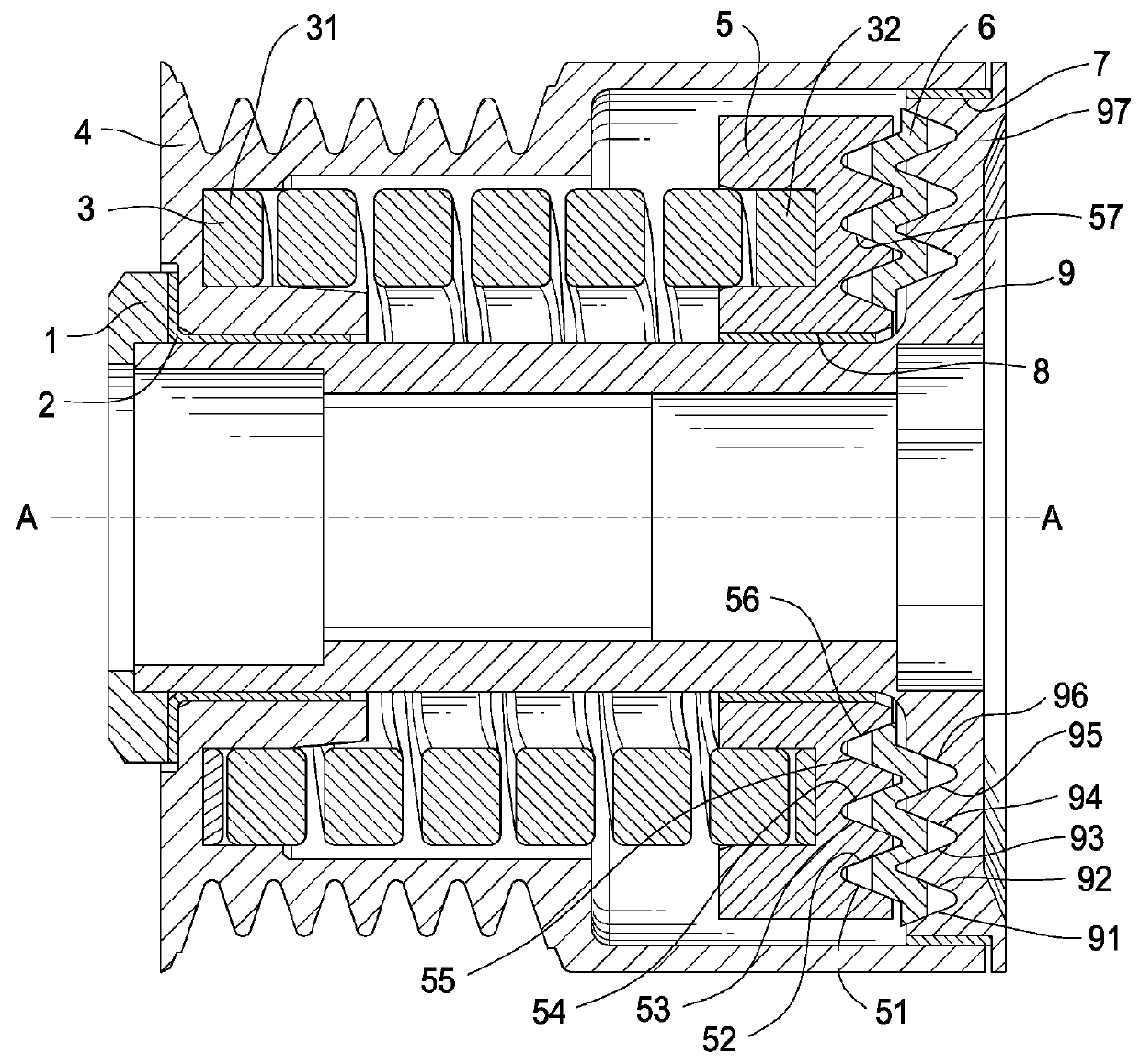
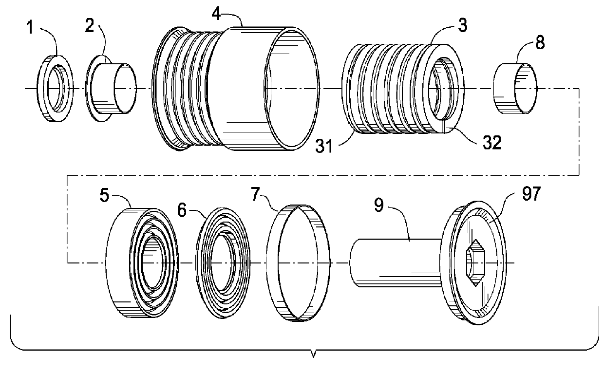
[0014]FIG. 1 is a cross-sectional view of the device. The device comprises a hub 9. Pulley 4 is journalled to and thereby rotatable about hub 9 on bush 2 and bush 7. Torsion spring 3 is engaged to pulley 4 and spring carrier 5. Spring carrier 5 is journalled to and thereby rotatably engaged with hub 9 through bush 8. Friction member 6 is frictionally disposed between with hub 9 and spring carrier 5. Cap 1 retains pulley 4 on hub 9.

[0015]Pulley 4 directly interfaces with a belt to drive the device. Power flows from pulley 4 to one end 31 of torsion spring 3 via an interference fit. Spring 3 is a biasing member that transmits torque and attenuates vibration and provides the isolating function of the device. Spring 3 transmits torque while being driven in an unwinding direction, but may also transmit torque in the winding direction in an alternate embodiment.

[0016]The other end 32 of spring 3 is connected to spring carrier 5. Spring carrier 5 has an interference fit to receive end 32 o...


PUM


Abstract

An isolating pulley comprising a hub, a pulley journalled to the hub, a spring carrier journalled to the hub, a torsion spring engaged between the pulley and the spring carrier, a frictionmember engaged between the spring carrier and the hub, the frictionmember comprising a first multiple ribbed surface to engage the spring carrier and a second multiple ribbed surface to engage the hub, and the first multiple ribbed surface and the second multiple ribbed surface extending in a radial direction normal to an axis of rotation A-A.

Description

FIELD OF THE INVENTION[0001]The invention relates to an isolating pulley, and more particularly, an isolating pulley comprising a friction member engaged between the spring carrier and the hub, the friction member comprising a first multiple ribbed surface to engage the spring carrier and a second multiple ribbed surface to engage the hub, each extending radially from an axis of rotation.BACKGROUND OF THE INVENTION[0002]Diesel engine use for passenger car applications is increasing due to the benefit of better fuel economy. Further, gasoline engines are increasing compression ratios to improve the fuel efficiency. As a result, diesel and gasoline engine accessory drive systems have to overcome the vibrations of greater magnitude from crankshafts due to above mentioned changes in engines.[0003]Due to increased crankshaft vibration plus high acceleration / deceleration rates and high alternator inertia the engine accessory drive system is often experiencing belt chirp noise due to belt ...

Claims


Application Information

Patent Timeline
Patent Type & Authority Patents(United States)
IPC IPC(8): F16H9/00F16H59/00F16H61/00F16H63/00F16D3/00F16H55/14F16H55/36F16H55/38F16D41/20
CPCF16H55/38F16D41/206F16H55/36F16H2055/366
Inventor WARD, PETER A.
Owner THE GATES CORP
Why Eureka
Try Eureka