Illuminating device
a technology of illumination device and light source, which is applied in the direction of shade, point-like light source, lighting and heating apparatus, etc., can solve the problems of insufficient illumination and discomfort of users, and achieve the effect of reducing brightness contrast and visual comfor
- Summary
- Abstract
- Description
- Claims
- Application Information
AI Technical Summary
Benefits of technology
Problems solved by technology
Method used
Image
Examples
first embodiment
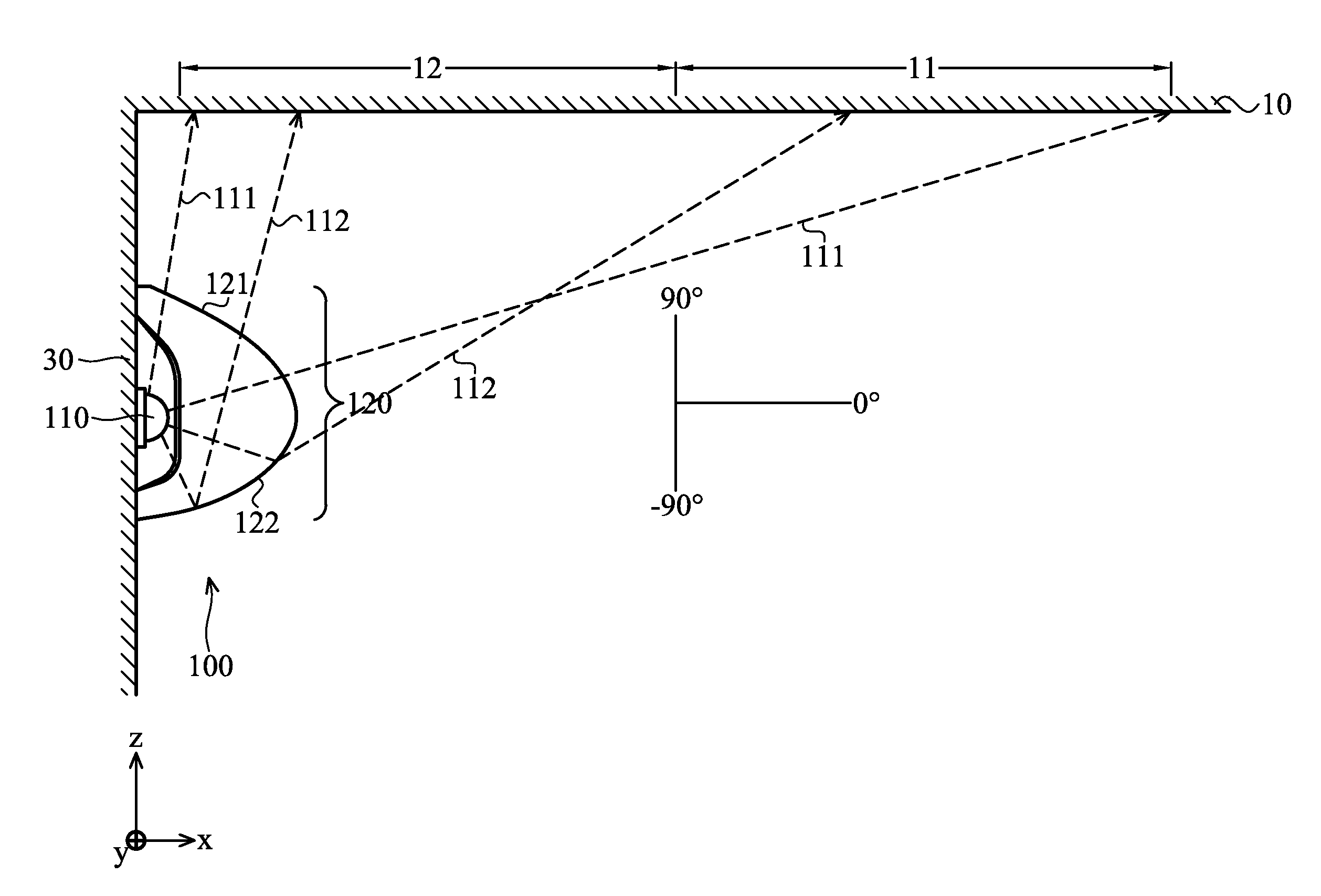
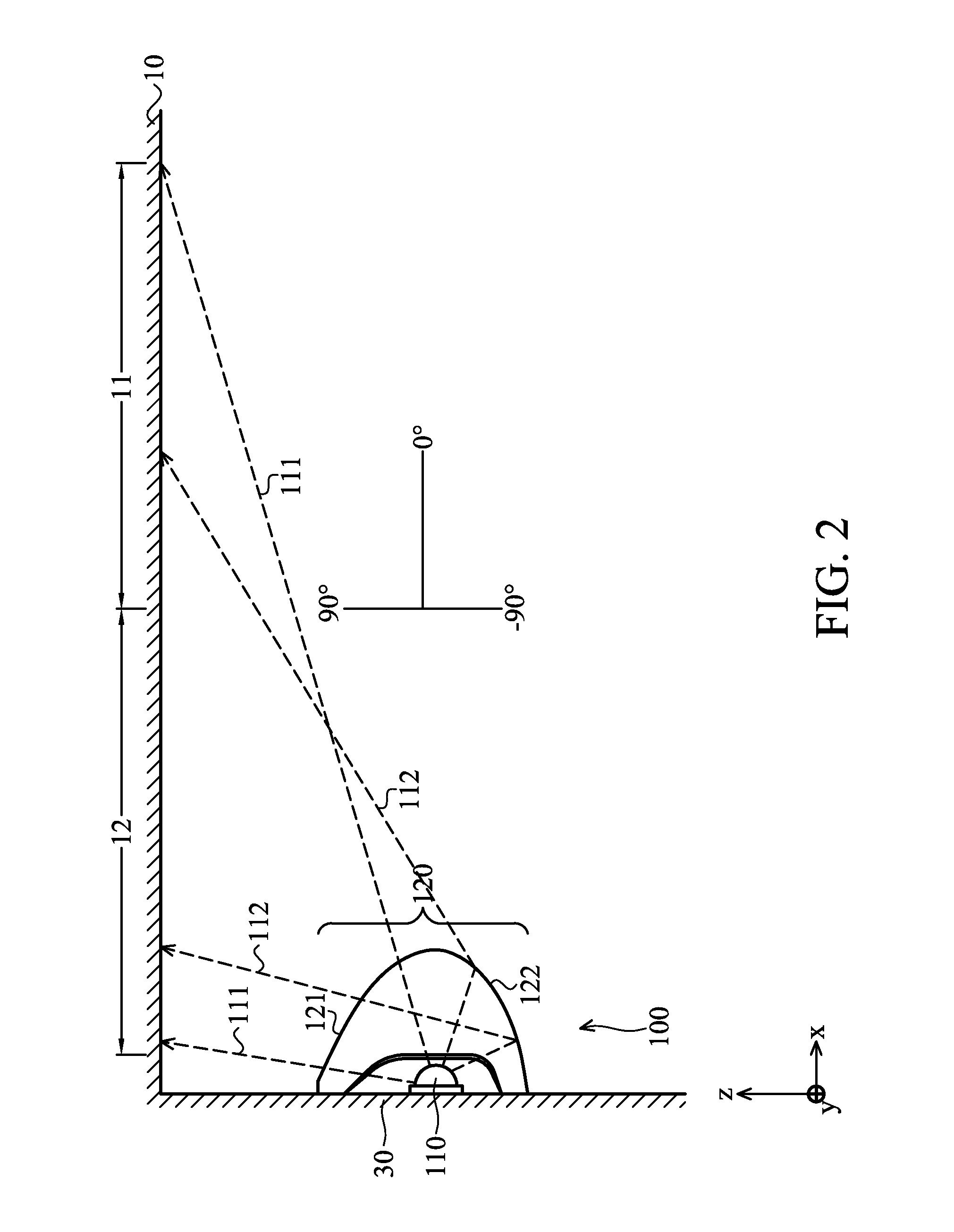
[0021]FIG. 2 shows an illuminating device 100 of a The illuminating device 100 includes a light source 110 and a lampshade 120. The light source 110 provides a first light beam 111 and a second light beam 112. The lampshade 120 includes a first curved surface 121 and a second curved surface 122. The first light beam 111 is substantially refracted by the first curved surface 121. The second light beam 112 is substantially reflected by the second curved surface 122. A curvature of the first curved surface 121 differs from that of the second curved surface 122. A light emitting angle of the first light beam 111 is between 90°˜0°. A light emitting angle of the second light beam 112 is between 0°˜−90°. In the embodiments, the light emitting angles are defined as an angle between the light beam and a normal line of the surface 30.
[0022]The illuminating device 100 is disposed in an inner space of a building. The space has a first body (ceiling, ground or wall) 10, and the first light beam...
second embodiment
[0029]In the second embodiment, light emitting angles of the first light beam 111′ and the second light beam 112′ are between 90°˜0°. Light emitting angles of the third light beam 113′ and the fourth light beam 114′ are between 0°˜90°. The space is formed by first body (ceiling, ground or wall) 10 and second body (wall or ceiling, ground) 20. The first light beam 111′ and the second light beam 112′ are projected to the first body (ceiling, ground or wall) 10. The third light beam 113 and the fourth light beam 114′ are projected to the second body (wall or ceiling, ground) 20. The second body (wall or ceiling, ground) 20 is substantially perpendicular to the first body (ceiling, ground or wall) 10.
[0030]In the second embodiment, a surface curvature of the first curved surface 121′ is negative, and an absolute value of the surface curvature of the first curved surface is greater than a reciprocal of the a distance between the light source 110′ and the first curved surface 121′. The fi...
third embodiment
[0034]FIG. 6 shows an illuminating device 100″ of a The illuminating device 100″ includes a light source 110″ and a lampshade 120″. The light source 110″ provides a first light beam 111″ and a second light beam 112″. The lampshade 120″ includes a first curved surface 121″ and a second curved surface 122″. The first light beam 111″ is substantially reflected by the first curved surface 121″. The second light beam 112″ is substantially reflected by the second curved surface 122″. The first curved surface 121″ is symmetric or asymmetric to the second curved surface 122″. A light emitting angle of the first light beam 111″ is between 90°˜0°. A light emitting angle of the second light beam 112″ is between 0°˜−90°.
[0035]Utilizing the illumination device 100″ of the third embodiment, the light beams provided thereby are uniformly reflected by a ceiling and a wall, and brightness contrast is further decreased. The illumination device 100″ of the third embodiment provides uniform illuminati...
PUM
 Abstract
Description
Claims
Application Information
 - R&D
- Intellectual Property
- Life Sciences
- Materials
- Tech Scout
- Unparalleled Data Quality
- Higher Quality Content
- 60% Fewer Hallucinations
Browse by: Latest US Patents, China's latest patents, Technical Efficacy Thesaurus, Application Domain, Technology Topic, Popular Technical Reports.
© 2025 PatSnap. All rights reserved.Legal|Privacy policy|Modern Slavery Act Transparency Statement|Sitemap|About US| Contact US: help@patsnap.com


