
Photoelectric rangefinders and measuring instruments including photoelectric rangefinders

A photoelectric rangefinder and optical amplifier technology, applied in the field of laser-like light sources, can solve the problems of effective averaging spot reduction, small size, etc.

Active Publication Date: 2019-08-13
HEXAGON TECH CENT GMBH
View PDF3 Cites 0 Cited by
  • Summary
  • Abstract
  • Description
  • Claims
  • Application Information

AI Technical Summary

Problems solved by technology

[0049] However, as the size of modern measuring instruments becomes ever smaller, effective averaging and thus spot reduction is not sufficient for itself

Method used


Image

  • Photoelectric rangefinders and measuring instruments including photoelectric rangefinders
  • Photoelectric rangefinders and measuring instruments including photoelectric rangefinders
  • Photoelectric rangefinders and measuring instruments including photoelectric rangefinders

Examples


Embodiment Construction

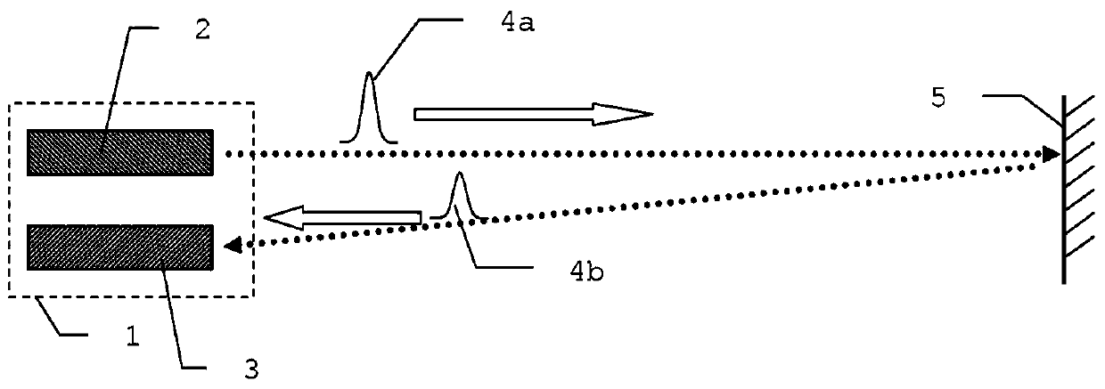
[0133]figure 1 A schematic diagram of an electro-optical distance measuring device 1 according to the pulse transit time principle is shown. A light emitting device 2 and a receiver 3 are arranged in the range finder 1 . The transmitter 2 emits a light pulse 4a, which is detected again by the receiver 3 after reflection or backscattering at a target 5 (eg, an object surface) as a backward defocused light pulse 4b. According to the invention, instead of light pulses, continuous modulation can also be used to transmit the signal.

[0134] The receiver 3 can here be constituted with a detector, such as an avalanche photodiode (APD), as is sufficiently known from the prior art, with signal processing electronics arranged downstream of the detector.

[0135] In a special embodiment, moreover, the design can also have a receiving diode formed from a plurality of segments, in particular a multi-segment PIN diode or APD. Such a design of a receiving diode for a distance meter is des...


PUM


Abstract

Optoelectronics and measuring instruments including photovoltaic distance measuring instruments.A ranging meter with a laser -like light source.The present invention involves a ranging meter for laser scanners, laser trackers, sections, latitudes, or full -bodies.In a specific embodiment of the present invention, the light source of the lapse of the pilot transmission of the pulsed light signal is set here to be set to the optical fiber amplifier (eDFA, that is, the mixing fiber amplifier).The ultra -radiation light emitting diode (SLD) operated by pulse is pumped in optical.

Description

technical field [0001] The invention relates to a laser-like light source for a rangefinder, in particular a laser-like light source for a laser scanner, profiler or theodolite. Background technique [0002] Various principles and methods are known in the field of electronic or optoelectronic distance measurement. One method involves emitting pulsed electromagnetic radiation (such as a laser, for example) at a target to be measured, and then receiving echoes from the target as scattered back objects, thereby, based on the transit time of the pulse, determining Determine the distance to the target to be measured. This pulse transit time measurement device had the advantage of being a standard solution in many fields at the time. [0003] However, current range finders equipped with laser sources (e.g. according to laser scanners with high measurement accuracy, in particular ground range noise) often exhibit artifacts such as intensity noise within the data point clouds gene...

Claims


Application Information

Patent Timeline
Patent Type & Authority Patents(China)
IPC IPC(8): G01C1/02G01C3/00G01S17/10
CPCG01C1/02G01C3/00G01S17/42G01S7/4818G01S7/484G01S7/4814G01S17/10H01S3/06754H01S5/3031
Inventor 雷托·施图茨J·辛德林
Owner HEXAGON TECH CENT GMBH
Learn More