
Heat sink fastening device and thermal module assembly using same

a technology of heat sink and fastening device, which is applied in the direction of semiconductor devices, lighting and heating apparatus, semiconductor device details, etc., can solve the problems of rising temperature, unstable performance of electronic elements, and the inability to easily operate conventional heat sink fastening devices with the above structure. achieve the effect of convenient and effortless operation

Active Publication Date: 2016-05-31
ASIA VITAL COMPONENTS SHENZHEN CO LTD
View PDF8 Cites 14 Cited by
  • Summary
  • Abstract
  • Description
  • Claims
  • Application Information

AI Technical Summary

Benefits of technology

[0007]A primary object of the present invention is to provide a thermal module assembly that includes at least one heat sink fastening device, with which the thermal module assembly can be quickly mounted onto or removed from a heat-producing electronic element without the need of using any hand tool or screws.
[0017]With the above arrangements, the heat sink fastening device of the present invention can be easily and effortlessly operated in a limited space to a fastened position for tightly attaching the heat sink of the thermal module assembly to the heat-producing electronic element, or to a released position to release the heat sink from the electronic element.

Problems solved by technology

The electronic elements operating at high speed also produce a large quantity of heat, which causes rising temperature and accordingly unstable performance of the electronic elements and the system using same.
The conventional heat sink fastening device with the above structure apparently could not be easily operated within a limited or narrow space in the miniaturized electronic product to fasten the heat sink to the heat-producing electronic element.

Method used


Image

  • Heat sink fastening device and thermal module assembly using same
  • Heat sink fastening device and thermal module assembly using same
  • Heat sink fastening device and thermal module assembly using same

Examples


Embodiment Construction

[0031]The present invention will now be described with some preferred embodiments thereof and with reference to the accompanying drawings. For the purpose of easy to understand, elements that are the same in the preferred embodiments are denoted by the same reference numerals.

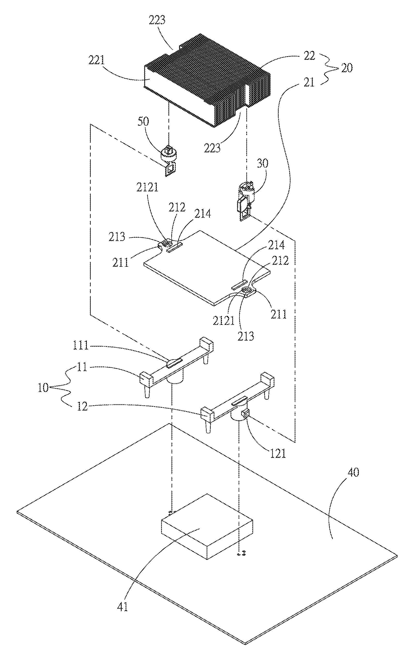
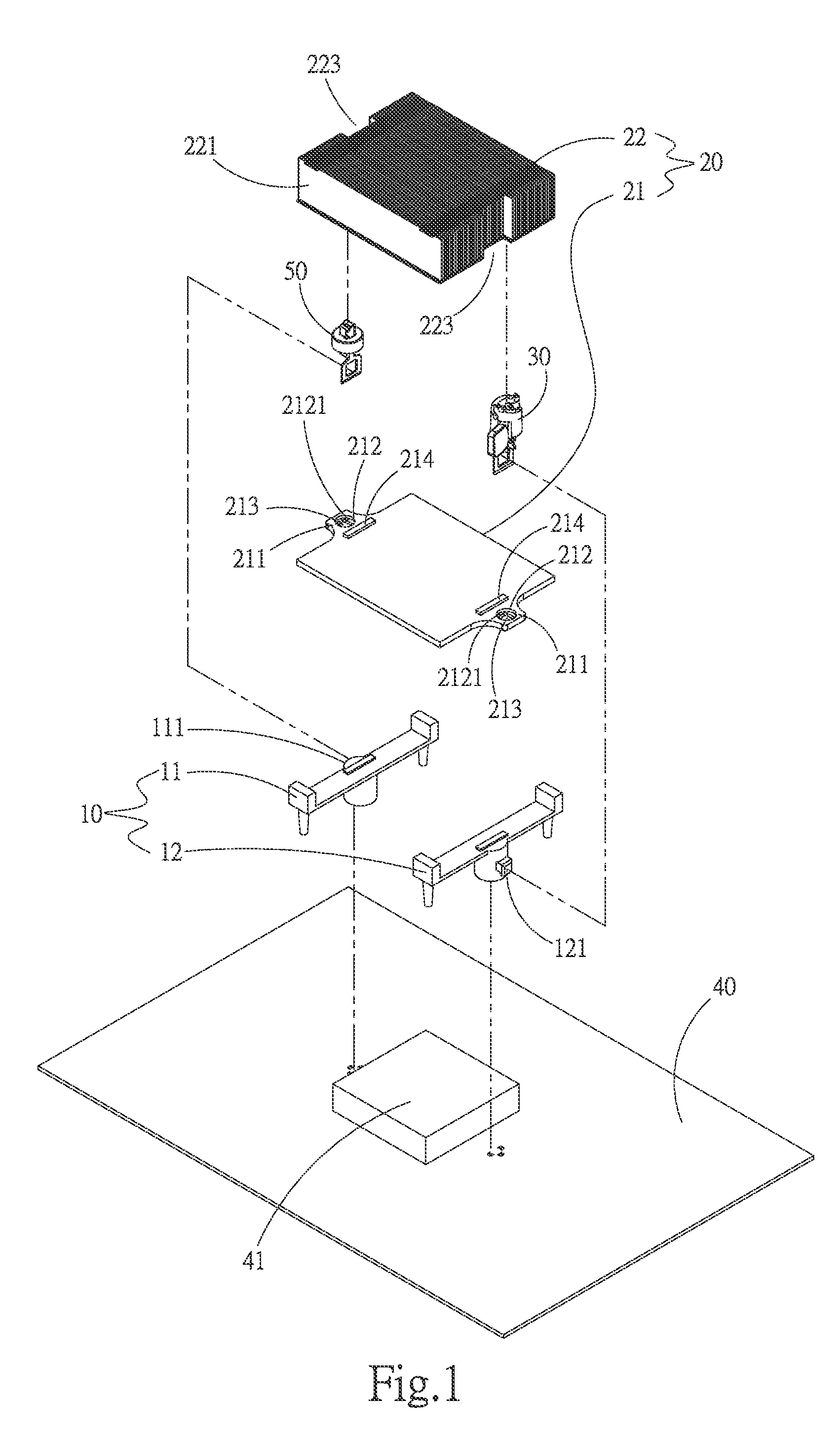
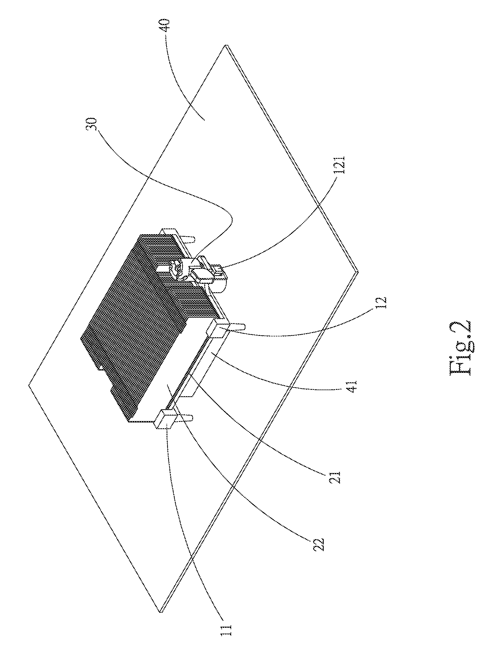
[0032]Please refer to FIGS. 1 and 2 that are exploded and assembled perspective views, respectively, of a thermal module assembly according to a preferred embodiment of the present invention. As shown, the thermal module assembly includes a mount 10, a heat sink 20, and a first heat sink fastening device 30. The mount 10 is connected onto a circuit board 40; the heat sink 20 is attached to a top surface of a heat-producing electronic element 41 mounted on the circuit board 40; and the first heat sink fastening device 30 is located on at least one side of the heat sink 20. A second heat sink fastening device 50 is located on another side of the heat sink 20 opposite to the first heat sink fastening device 30. By...


PUM


Abstract

A heat sink fastening device includes an operating member and a retaining member axially extended through the operating member and associated with the latter via a pivot shaft. The operating member includes a cylindrical cam portion, which has an elastic element received therein to provide the cam portion with an elastic force. The cam portion has an upper end formed into a pair of cam surfaces, on which the pivot shaft is rested. The operating member can be horizontally rotated about an axis thereof. When the operating member is rotated, the cam surfaces rotate and cause the pivot shaft to move from a higher to a lower position on the cam surfaces or vice versa, so that the retaining member associated with the operating member via the pivot shaft is brought by the pivot shaft to axially move downward to a released position or upward to a fastened position.

Description

FIELD OF THE INVENTION[0001]The present invention relates to a heat sink fastening device, and more particularly to a heat sink fastening device for fixedly attaching a heat sink onto a heat-producing electronic element. The present invention also relates to a thermal module assembly that uses the above-mentioned heat sink fastening device.BACKGROUND OF THE INVENTION[0002]The rapidly developed electronic industry enables electronic elements to have constantly increased operating speed. The electronic elements operating at high speed also produce a large quantity of heat, which causes rising temperature and accordingly unstable performance of the electronic elements and the system using same. Normally, to ensure normal and stable operation of a heat-producing electronic element, a heat-dissipation device is mounted on the electronic element to remove the produced heat from the electronic element.[0003]Currently, to solve the heat dissipation problem thereof, every heat-producing elec...

Claims


Application Information

Patent Timeline
Patent Type & Authority Patents(United States)
IPC IPC(8): H01L23/34F28D15/02F28F99/00H01L23/40
CPCF28F99/00F28D15/0275H01L23/34F28F2275/08H01L2924/0002H01L23/4006H01L2023/405H01L2023/4081H01L2023/4087H01L2924/00
Inventor LIN, SHENG-HUANG
Owner ASIA VITAL COMPONENTS SHENZHEN CO LTD
Learn More