
Undulator with dynamic compensation of magnetic forces

a technology of dynamic compensation and magnetic force, applied in the field ofundulators, can solve the problem that the designers of ids have not taken real advantage of it so far

Active Publication Date: 2016-05-31
UCHICAGO ARGONNE LLC
View PDF6 Cites 0 Cited by
  • Summary
  • Abstract
  • Description
  • Claims
  • Application Information

AI Technical Summary

Benefits of technology

This patent describes a way to make spring cages that can generate a compensation force that is both reliable and repeatable. The invention allows for this by using a specific mechanical design.

Problems solved by technology

Although e-beam in FELs is quite symmetric in the transverse plane, ID designers have not taken real advantage of it so far.

Method used


Image

  • Undulator with dynamic compensation of magnetic forces
  • Undulator with dynamic compensation of magnetic forces
  • Undulator with dynamic compensation of magnetic forces

Examples


Embodiment Construction

[0031]In the following detailed description of embodiments of the invention, reference is made to the accompanying drawings, which illustrate example embodiments by which the invention may be practiced. It is to be understood that other embodiments may be utilized and structural changes may be made without departing from the scope of the invention.

[0032]The terminology used herein is for the purpose of describing particular embodiments only and is not intended to be limiting of the invention. As used herein, the singular forms “a”, “an” and “the” are intended to include the plural forms as well, unless the context clearly indicates otherwise. It will be further understood that the terms “comprises” and / or “comprising,” when used in this specification, specify the presence of stated features, integers, steps, operations, elements, and / or components, but do not preclude the presence or addition of one or more other features, integers, steps, operations, elements, components, and / or gr...


PUM

PropertyMeasurementUnit
magnetic forcesaaaaaaaaaa
lengthaaaaaaaaaa
mechanical forceaaaaaaaaaa

Abstract

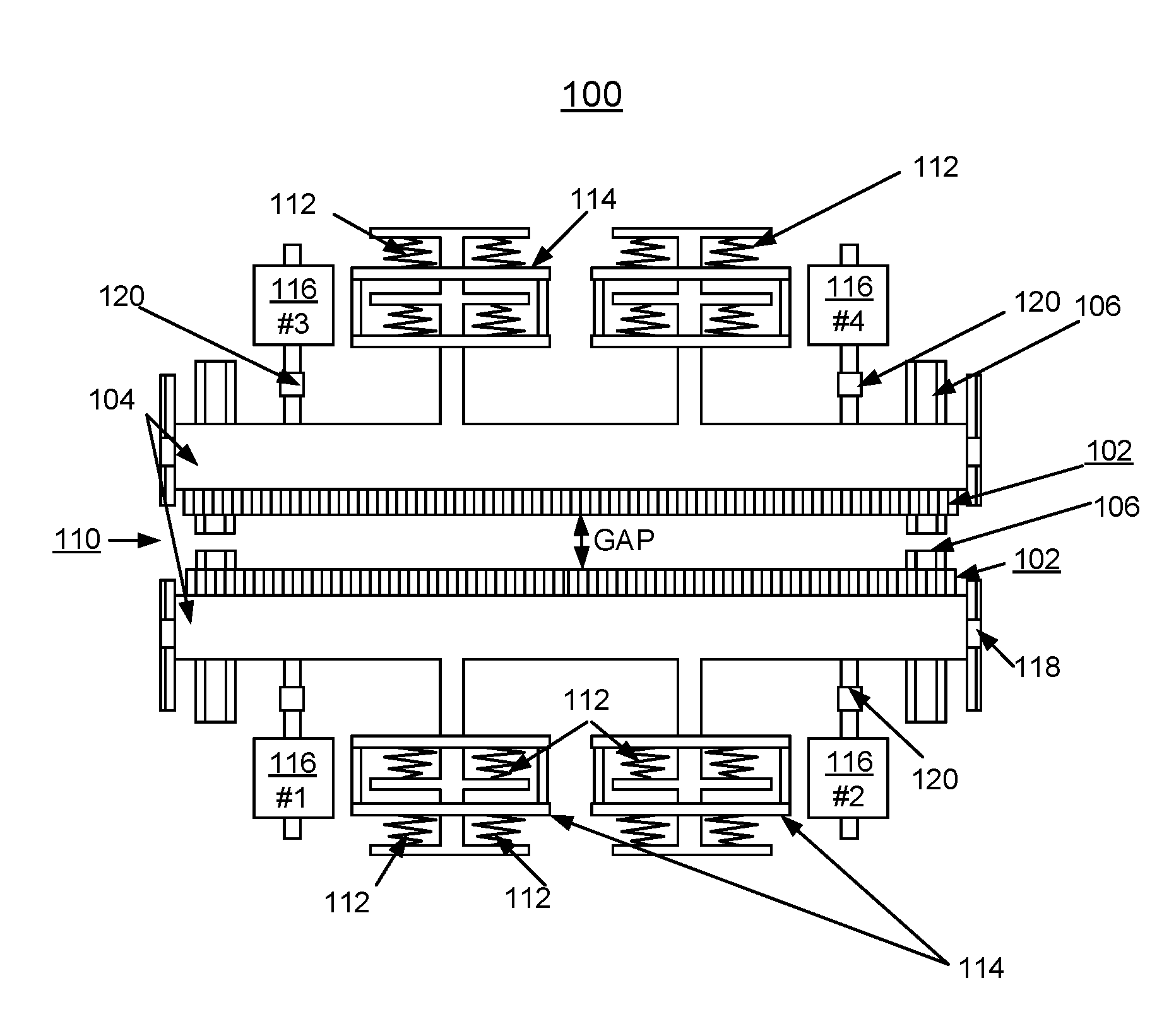
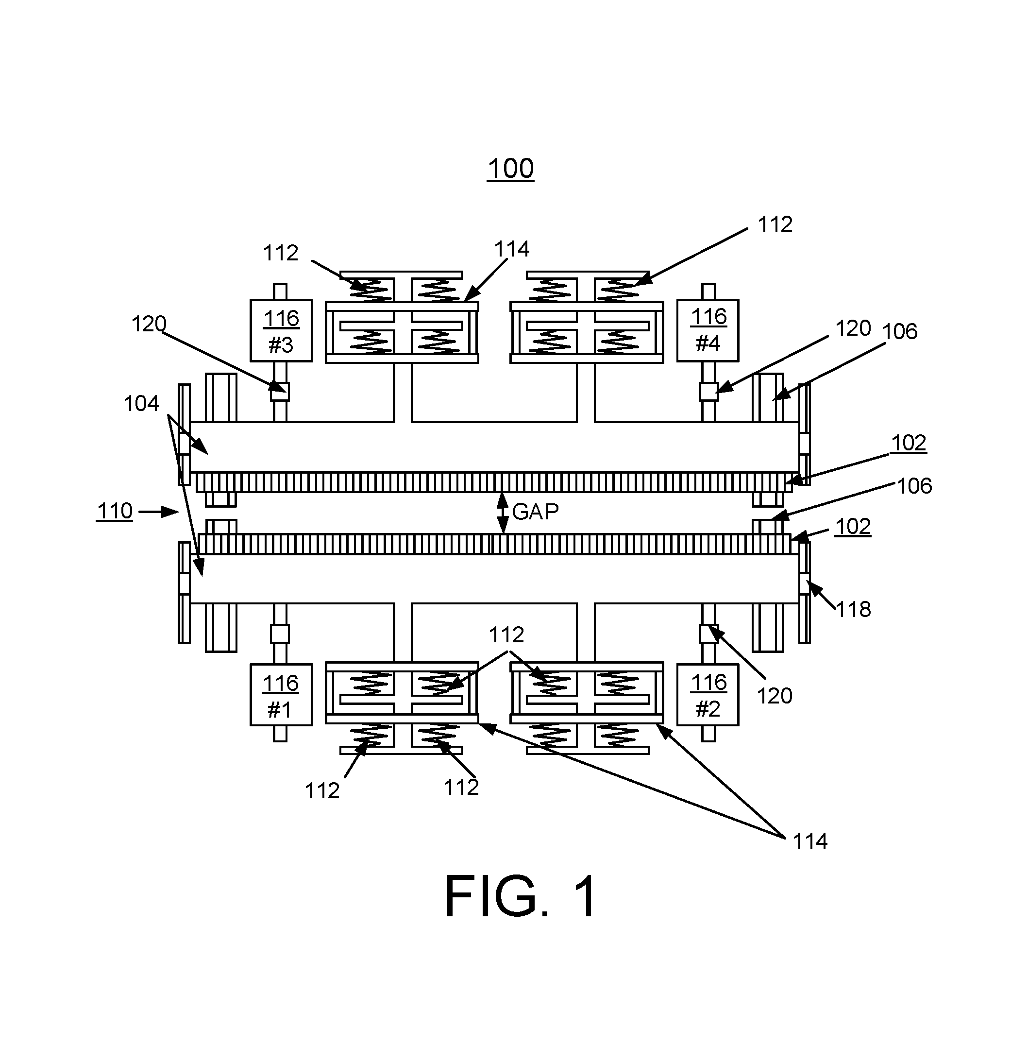
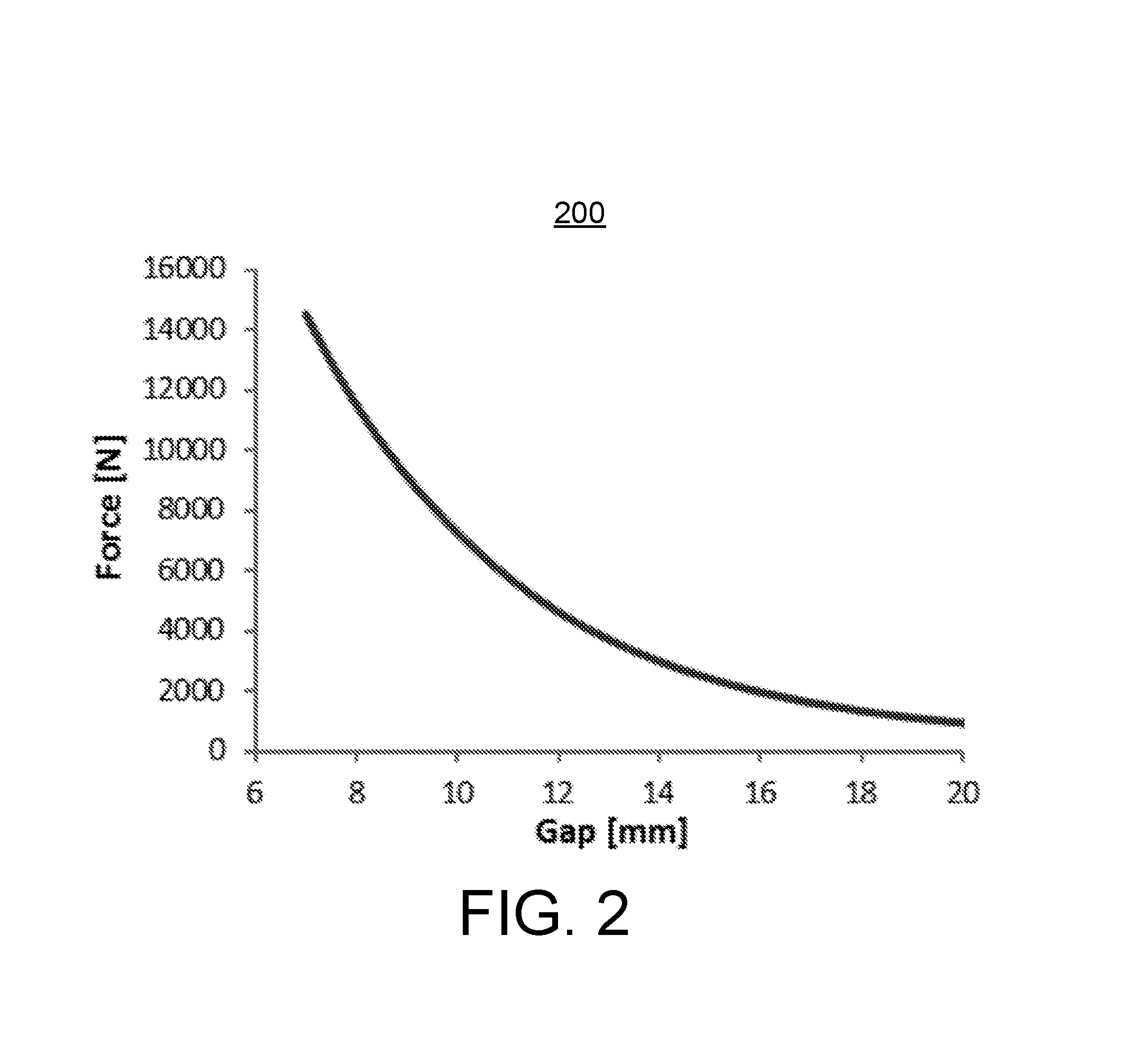
A method and apparatus for implementing dynamic compensation of magnetic forces for undulators are provided. An undulator includes a respective set of magnet arrays, each attached to a strongback, and placed on horizontal slides and positioned parallel relative to each other with a predetermined gap. Magnetic forces are compensated by a set of compensation springs placed along the strongback. The compensation springs are conical springs having exponential-force characteristics that substantially match undulator magnetic forces independently of the predetermined gap. The conical springs are positioned along the length of the magnets.

Description

CONTRACTUAL ORIGIN OF THE INVENTION[0001]The United States Government has rights in this invention pursuant to Contract No. DE-AC02-06CH11357 between the United States Government and UChicago Argonne, LLC representing Argonne National Laboratory.FIELD OF THE INVENTION[0002]The present invention relates generally to undulators for synchrotron radiation and free electron laser (FEL) sources, and more particularly, relates to a method and apparatus for implementing dynamic compensation of magnetic forces for undulators.DESCRIPTION OF THE RELATED ART[0003]A known synchrotron radiation source is the Advanced Photon Source (APS) at Argonne National Laboratory. The Advanced Photon Source (APS) at Argonne National Laboratory is a national synchrotron-radiation light source research facility. Utilizing high-brilliance x-ray beams from the APS, members of the international synchrotron-radiation research community carry out forefront basic and applied research in the fields of materials scienc...

Claims


Application Information

Patent Timeline
Patent Type & Authority Patents(United States)
IPC IPC(8): H01F7/02H05H7/04
CPCH01F7/0231H01F7/0221H01F7/0278H05H7/04H05H2007/041
Inventor GLUSKIN, EFIMTRAKHTENBERG, EMILXU, JOSEPH Z.
Owner UCHICAGO ARGONNE LLC
Learn More