Electrical connector

a technology of electrical connectors and connectors, applied in the direction of coupling device connections, coupling protective earth/shielding arrangements, two-part coupling devices, etc., can solve the problems of operator difficulty in determining with eyes whether the terminals are properly assembled, weak structural strength of the terminals, and false installation of the terminals on the insulative base, etc., to achieve better anti-electromagnetic interference effects and enhance overall assembly yield

Active Publication Date: 2016-05-31
CHANT SINCERE CO LTD
View PDF4 Cites 18 Cited by
  • Summary
  • Abstract
  • Description
  • Claims
  • Application Information

AI Technical Summary

Benefits of technology

[0014]According to one embodiment of the present invention, the second section of the internal conductive sheet includes a plurality of resistant contacts, which are used to contact a corresponding electrical connector to increase the plug strength between the two.
[0019]According to the above-mentioned structures, the electrical connector of the present invention provides the external conductive sheet between the first terminals and the second terminals to prevent the signal which is sent from the first terminals and the signal which is sent from the second terminals from being interfered with one another. Moreover, the present invention is which disposes the top complex and the bottom complex with the upper internal conductive sheet and the lower internal conductive sheet respectively, and disposes the casing to cover the above-mentioned components to provide the electrical connector with better anti-electromagnetic interference effects. Besides, the assembly of the electrical connector of the present invention begins with inserting the first terminals, the external conductive sheet, and the second terminals into the top complex, the center complex, and the bottom complex respectively via a production method such as Insert-Molding process, and thereafter performs a step of assembling the top complex, the center complex, and the bottom complex together. Next, the conductive tail and the partial portion of the second terminals that is disposed at a position far away from the opening of the casing are covered with the block, and finally the first positioning protrude of the upper internal conductive sheet and the second positioning protrude of lower internal conductive sheet are inserted into the first engagement hole and the second engagement hole of the center complex in such a manner that after the upper internal conductive sheet and the lower internal conductive sheet are disposed at a side of the top complex and the center complex, the upper internal conductive sheet and the lower internal conductive sheet together with the top complex and the center complex are inserted into the casing. The configuration structure of the present invention and the above-mentioned assembly methods can effectively enhance the overall assembly yield.

Problems solved by technology

Furthermore, since the terminals are narrowed in width, the structural strength of the terminals becomes weaker.
When this kind of electrical connector is being assembled, the differences among the strengths exerted on the terminals by different operators may lead to a bend or a curve in the terminals and a false installation of the terminals on the insulative base.
In addition, since the terminal width is very small and the number of terminals is quite large, the operators have difficulties determining with eyes whether the terminals are properly assembled.
Therefore, such kind of electrical connector has higher defect rate.

Method used


Image

  • Electrical connector
  • Electrical connector
  • Electrical connector

Examples


Embodiment Construction

)

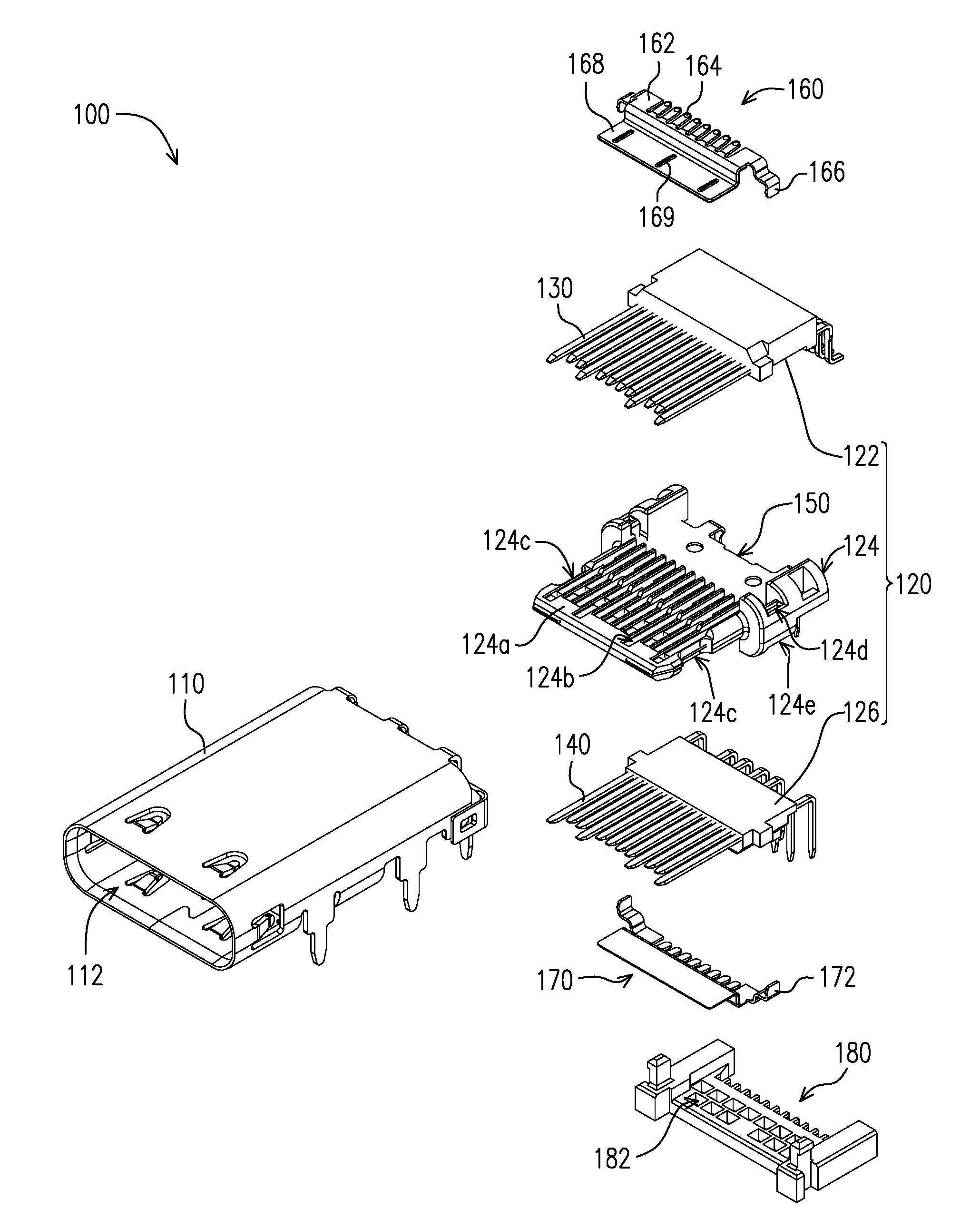
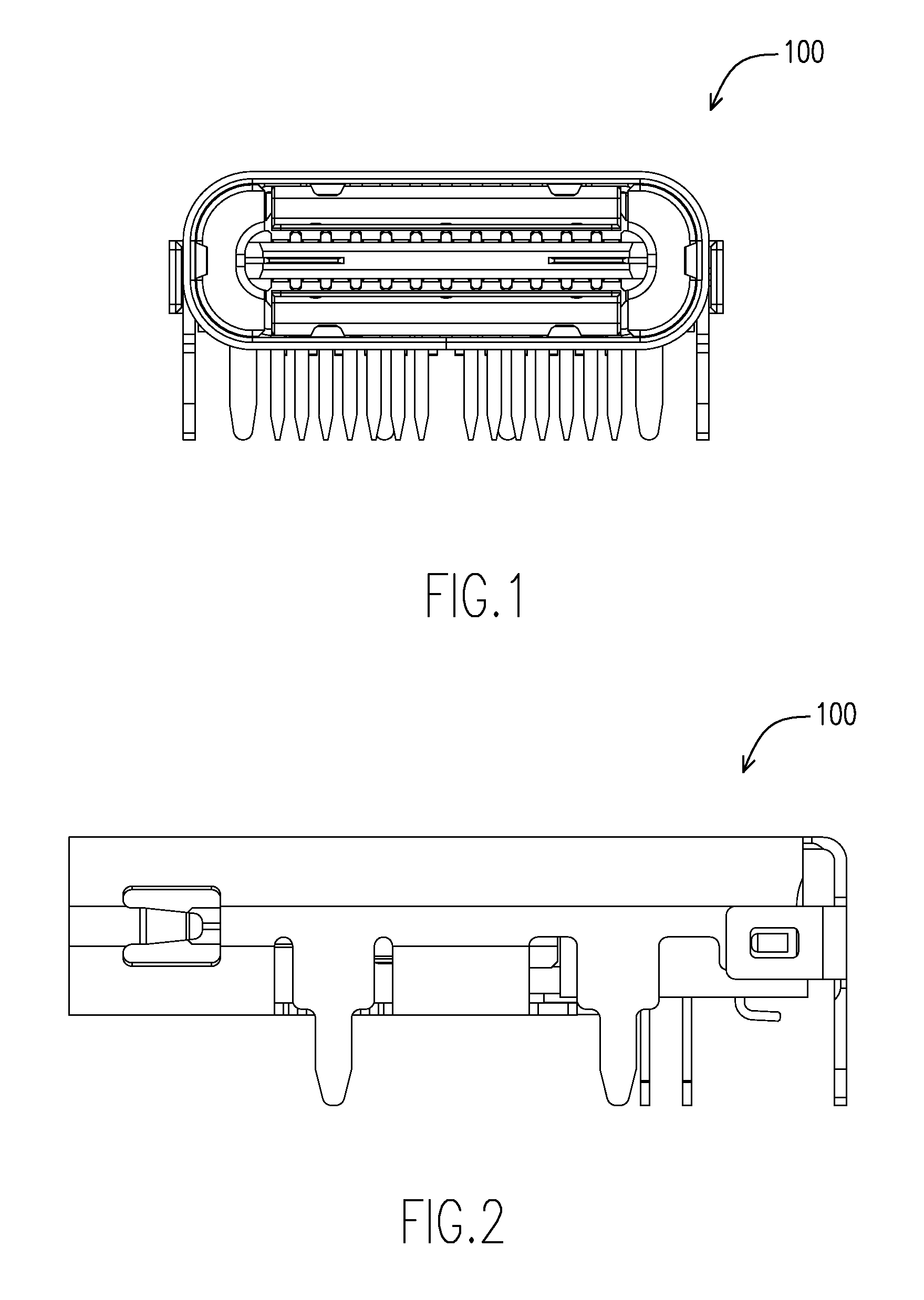
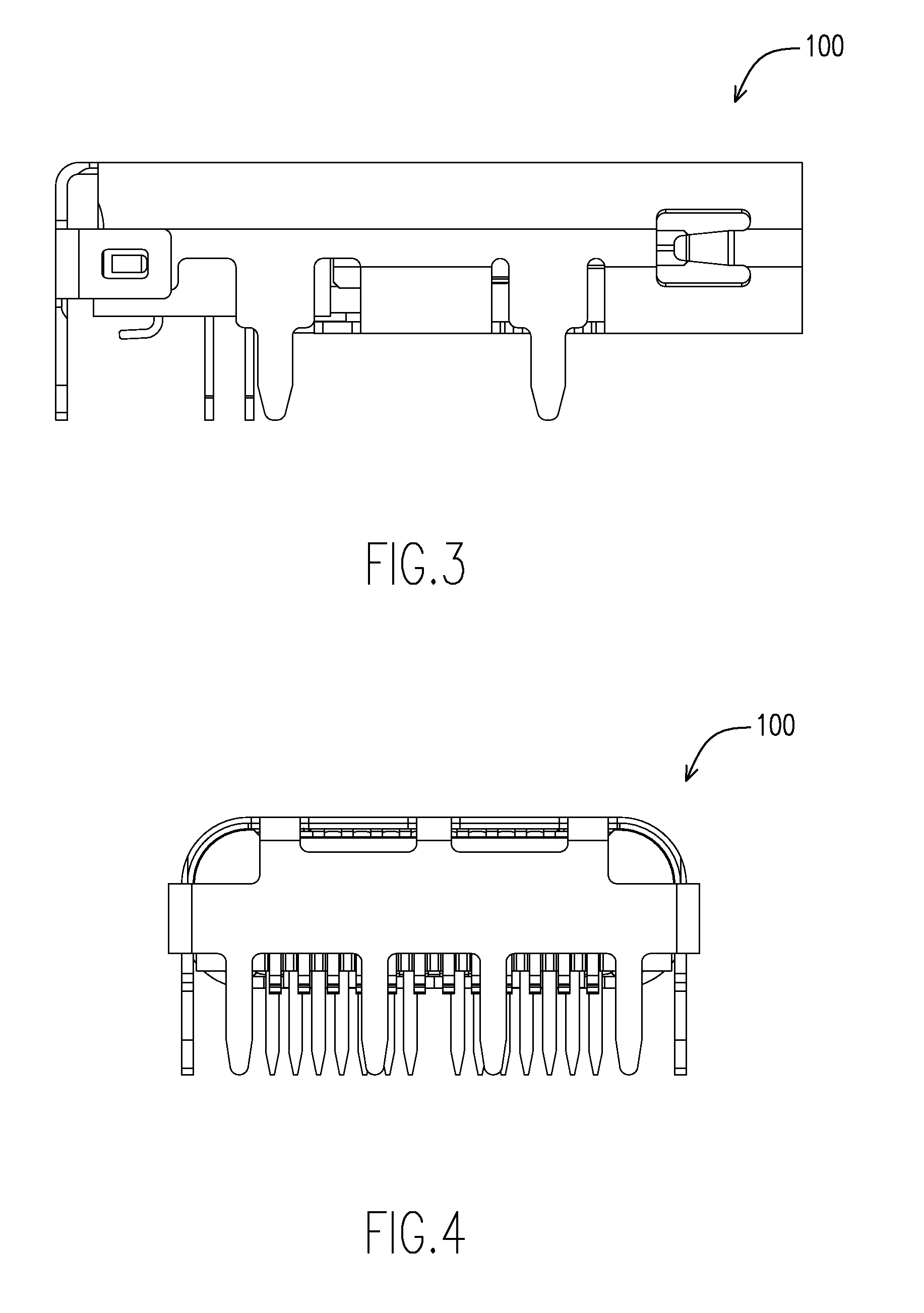
[0033]FIG. 1 is a schematic diagram of an electrical connector 100 according to one embodiment of the present invention. FIG. 2 to FIG. 4 are schematic diagrams of the electrical connector 100 shown in FIG. 1 viewed from different angles. More specifically, FIG. 1 is a front view of the electrical connector 100 according to this embodiment, and FIG. 2, FIG. 3 are respectively the left side view and the right side view of the electrical connector 100 according to this embodiment. FIG. 4 is a back side view of the electrical connector 100 according to this embodiment. In this embodiment, the electrical connector 100 is a female USB C type connector, but the present invention does not limit the type of the electrical connector 100.

[0034]The detailed components of the electrical connector 100 according to this embodiment are shown in FIG. 5 and FIG. 6. FIG. 5 is an exploded perspective view of the electrical connector 100 shown in FIG. 1. FIG. 6 is a schematic diagram of the electrical...


PUM


Abstract

An electrical connector comprises an external conductive sheet, an upper internal conductive sheet, a lower internal conductive sheet and the necessary others. An insulative base is disposed within a casing and includes a top complex, a center complex, and a bottom complex in sequential connection. The upper internal conductive sheet and the lower internal conductive sheet are fixed to the insulative base. Thereafter, an improving electrical connector interface is provided.

Description

CROSS-REFERENCE TO RELATED APPLICATIONS[0001]This application claims the benefit of the filing date under 35 U.S.C. §119(a)-(d) of Taiwan Patent Application No. 103214719, filed Aug. 18, 2014.BACKGROUND OF THE INVENTION[0002]1. Field of the Invention[0003]The present invention relates to an electrical connector.[0004]2. Description of the Related Art[0005]As technology advances, the sizes of electrical connectors are getting smaller and smaller, and the number of terminals increases with the upgrade of the transmission specifications. Take one of the new electrical connector specifications (USB C type connector) as an example: the overall size of a USB C type electrical connector is smaller than the USB 2.0 electrical connector, and the USB C type electrical connector has two rows of terminals, in which the number of terminals in each row is 12.[0006]In other words, a USB C type connector includes a larger amount of terminals needed to be disposed in a smaller space (the insulative ...

Claims


Application Information

Patent Timeline
Patent Type & Authority Patents(United States)
IPC IPC(8): H01R13/648H01R24/60H01R13/6585H01R13/506H01R13/6594H01R107/00
CPCH01R24/60H01R13/6585H01R13/506H01R13/6594H01R2107/00H01R13/6581
Inventor YEN, MING HUIHSU, CHUN-HSIANG
Owner CHANT SINCERE CO LTD
Why Eureka
Try Eureka