
Internal magnetic core connecting line

A technology of connecting wire and magnetic core, applied in the field of data transmission, can solve the problems of poor anti-electromagnetic wave interference effect, affecting product quality, complex processing technology, etc., achieving the effect of less processing technology, saving raw materials, and reducing injection molding of magnetic cores

Inactive Publication Date: 2009-12-02
WEIHAI HONGLIN ELECTRIC POWER TECH CO LTD
View PDF0 Cites 0 Cited by
  • Summary
  • Abstract
  • Description
  • Claims
  • Application Information

AI Technical Summary

Problems solved by technology

[0002] As we all know, there are more and more data connection lines for analog and digital products such as computers, video cameras, cameras and televisions. This kind of data connection line is a short-distance connection line. The shape of the connector can be divided into sockets, plugs and modular multiple terminal boards, and some are called plug-in strips and inserts. , sockets and other components are connected to the connecting wires, and the shell is generally made of PVC plastic injection molding. The electromagnetic wave interference of the connecting wires is becoming more and more prominent and has become the largest environmental pollution problem in the world today, which has affected people's physical and mental health to varying degrees. Health also affects the quality of the product. In order to ensure the quality of data transmission, people have many structural modifications and strict control measures in the anti-electromagnetic interference of short-distance connecting lines. For example, it is an effective The anti-electromagnetic interference measures, but this set of magnetic cores are far away from the connector, the anti-electromagnetic interference effect is poor, and it needs to be processed in the early stage and then glued to the connecting wire. The processing technology is complicated and the cost is high.

Method used


Image

  • Internal magnetic core connecting line
  • Internal magnetic core connecting line

Examples


Embodiment Construction

[0009] The present invention will be further described below in conjunction with accompanying drawing:

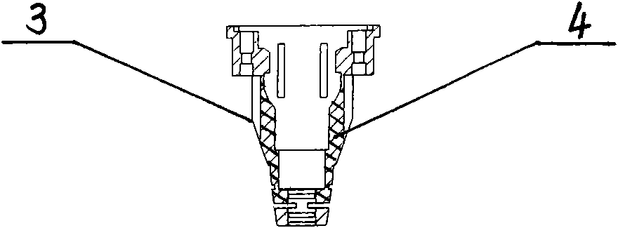
[0010] As shown in the drawings, a connecting wire with a built-in magnetic core is provided with a connecting wire 1, and the two ends of the connecting wire are respectively connected with connectors 2. The structures of the connecting wire 1 and the connector 2 and the interconnection relationship between them are similar to those of the prior art. The same, this will not go into details, the feature of the present invention is that the housing 3 of the joint 1 is provided with a magnetic core 4, and the housing 3 is injection molded with PVC plastic. When injection molding, the magnetic core 4 is directly placed in the injection mold cavity and injected with PVC. The joint housing is made, so that the magnetic core 4 is buried in the housing 3, so that the magnetic core 3 is in the joint 2, the distance is zero, and the shielding effect is good. The present invention has...


PUM


Abstract

The invention relates to the technical field of data transmission, in particular to an internal magnetic core connecting line with electromagnetic interference prevention. The internal magnetic core connecting line is provided with a connecting line, and a joint is respectively connected with both ends of the connecting line. The internal magnetic core connecting line is characterized in that because a shell of each joint connected with the connecting line is internally provided with a magnetic core, the magnetic core is directly arranged in an injection mould cavity to be manufactured into a joint shell by using PVC injection, and then a wire and a tinplate penetrate through the injection shell to be connected with a wire and a D-SUB joint in a cable, therefore, the magnetic core injection is reduced, and the invention has the advantages of favorable anti-electromagnetic interference effect, little machining process, low machining cost, raw material saving, easy guarantee of product quality, and the like.

Description

Technical field: [0001] The invention relates to the technical field of data transmission, in particular to a built-in magnetic core connection line for preventing electromagnetic wave interference. Background technique: [0002] As we all know, there are more and more data connection lines for analog and digital products such as computers, video cameras, cameras and televisions. This kind of data connection line is a short-distance connection line. The shape of the connector can be divided into sockets, plugs and modular multiple terminal boards, and some are called plug-in strips and inserts. , sockets and other components are connected to the connecting wires, and the shell is generally made of PVC plastic injection molding. The electromagnetic wave interference of the connecting wires is becoming more and more prominent and has become the largest environmental pollution problem in the world today, which has affected people's physical and mental health to varying degrees....

Claims


Application Information

Patent Timeline
Patent Type & Authority Applications(China)
IPC IPC(8): H01R11/11H01R31/06H01R13/658
Inventor 郭亮才
Owner WEIHAI HONGLIN ELECTRIC POWER TECH CO LTD
Learn More