
Electronic device

Inactive Publication Date: 2019-09-12
PEGATRON
View PDF6 Cites 0 Cited by
  • Summary
  • Abstract
  • Description
  • Claims
  • Application Information

AI Technical Summary

Benefits of technology

The present patent provides an electronic device with a convenient manufacturing process that also has an effective anti-electromagnetic interference (EMI) effect. The device has a larger grounding area than conventional copper pillars, which leads to better EMI protection.

Problems solved by technology

In this case, a manufacturer needs to dispose the copper pillars on the circuit board one by one, making a manufacturing process relatively troublesome.
However, limited by the size of the copper pillar, a grounding area that can be provided is relatively small, and an anti-electromagnetic interference effect of the expansion card is affected accordingly.

Method used


Image

  • Electronic device
  • Electronic device
  • Electronic device

Examples


Embodiment Construction

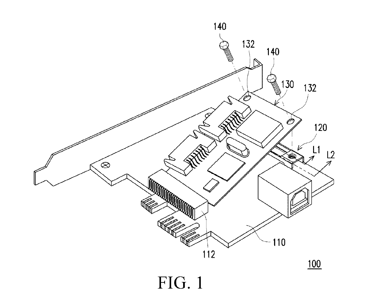
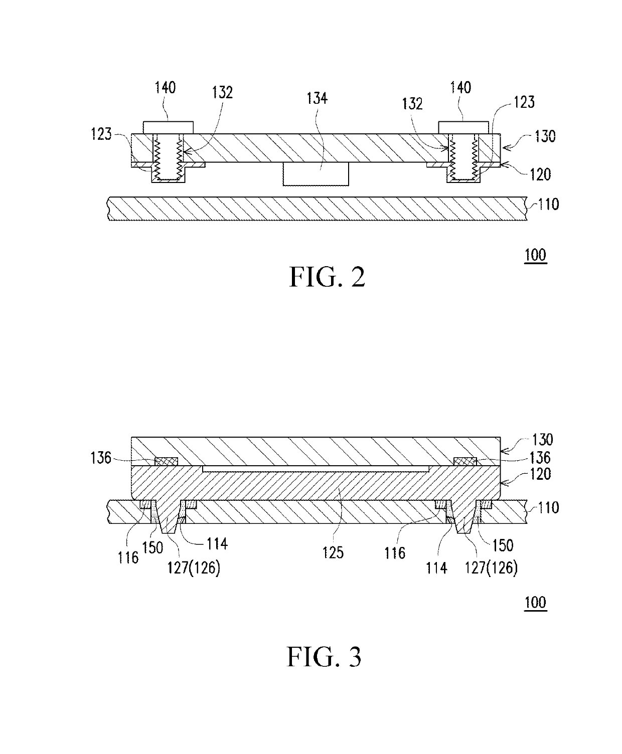
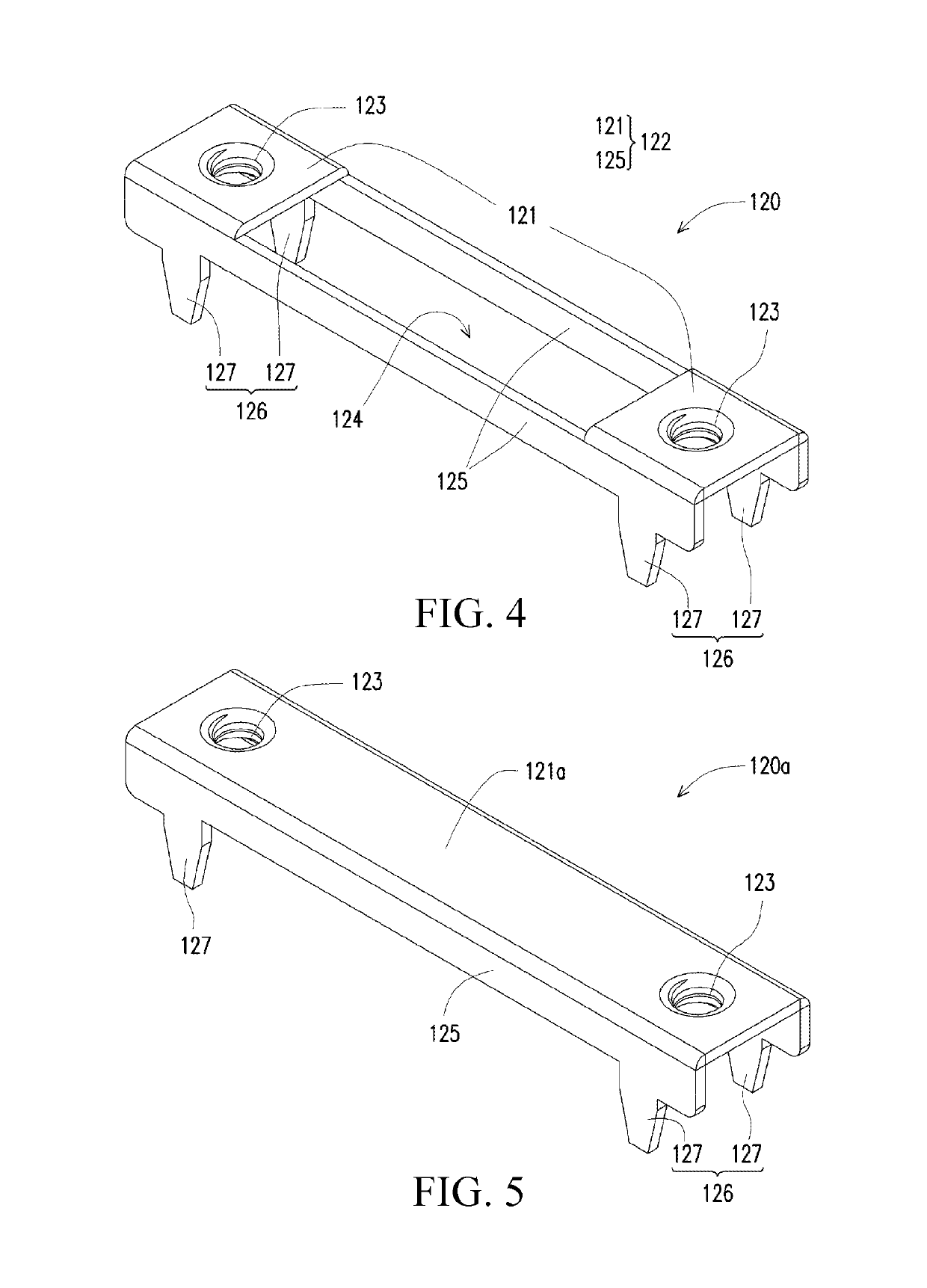
[0023]FIG. 1 is a three-dimensional schematic diagram in which an expansion card of an electronic device has not been fixed by a locking piece according to an embodiment of the present disclosure. FIG. 2 is a schematic diagram of a cross section along a line segment L1 when the expansion card of the electronic device in FIG. 1 is fixed by a locking piece to a circuit board. FIG. 3 is a schematic diagram of a cross section along a line segment L2 when the expansion card of the electronic device in FIG. 1 is fixed by a locking piece to a circuit board. FIG. 4 is a three-dimensional schematic diagram of a conductive piece of the electronic device in FIG. 1.

[0024]Referring to FIG. 1 to FIG. 4 together, in this embodiment, the electronic device 100 includes a circuit board 110, a conductive piece 120 fixedly disposed on the circuit board 110, an expansion card 130 that is detachably disposed on the circuit board 110 and that abuts the conductive piece 120, and at least one locking piece ...


PUM


Abstract

An electronic device includes a circuit board and a conductive piece. The circuit board includes a hole and a grounding pad close to the hole. The conductive piece includes an insertion component and an enlarged grounding portion connected to the insertion component. The insertion component of the conductive piece is inserted into the hole of the circuit board and is electrically connected to the grounding pad, and a size of the enlarged grounding portion is larger than that of the hole.

Description

CROSS-REFERENCE TO RELATED APPLICATION[0001]This application claims priority to Taiwan Application Serial Number 107107963, filed Mar. 8, 2018, which is herein incorporated by reference in its entirety.BACKGROUNDTechnical Field[0002]The present disclosure relates to an electronic device, and in particular, to an electronic device that is manufactured conveniently and has a better anti-electromagnetic interference effect.Related Art[0003]Currently, when an expansion card (for example, a mini PCI-E expansion card) is mounted onto a circuit board, one side of the expansion card is inserted into a connector on the circuit board, and the other side of the expansion card is further locked onto the circuit board by using a screw, so that the expansion card may be stably fixed to the circuit board. Therefore, a designer usually disposes a copper pillar having a screw hole at a location on the circuit board corresponding to the screw. However, if a plurality of screws needs to be used for fi...

Claims


Application Information

Patent Timeline
IPC IPC(8): H05K7/14H05K7/10H05K7/02H05K1/02G06F13/42
CPCG06F13/4221H05K7/026H05K7/1407G06F2213/0026H05K1/0216H05K7/10H05K1/0215G06F13/4022G06F13/4081G06F13/4295H05K2201/10409G06F1/185
Inventor WU, PING-CHUNGTSAO, WEI-CHUNYANG, YAO-CHIANG
Owner PEGATRON
Learn More