Torsional resonance frequency adjustor

a technology of torsional resonance frequency and adjustor, which is applied in the direction of vibration suppression adjustment, rotating body balancing, flywheel, etc., can solve the problems of adding time and complexity to the process, adding to the complexity and time involved

Active Publication Date: 2016-06-14
GE INFRASTRUCTURE TECH INT LLC
View PDF52 Cites 2 Cited by
  • Summary
  • Abstract
  • Description
  • Claims
  • Application Information

AI Technical Summary

Benefits of technology

[0005]Another embodiment may include a torsional frequency adjustor for a rotating body, the torsional frequency adjuster including an inner ring with an inner total arcuate length smaller than an outer total arcuate length of the rotating body. The inner ring can have a longitudinal center with a largest outer diameter of the inner ring, a front portion extending from a longitudinal front edge to the longitudinal center, and a rear portion of the inner ring extending from the longitudinal center to a rear longitudinal edge. The longitudinal front edge can have an outer diameter that is smaller than the largest outer diameter, as can the longitudinal rear edge. The adjustor may additionally include at least two front outer rings sized to engage an outer surface of the front portion of the inner ring and at least two rear outer rings sized to engage an outer surface of the rear portion of the inner ring. Each front outer ring can include an inner surface corresponding to at least a part of the outer surface of the front portion of the inner ring so that when the at least two front outer rings are engaging each other in a longitudinal direction, the combined inner surfaces of the at least two front outer rings form a substantially contiguous inner surface selectively engaging the outer surface of the front portion of the inner ring. Similarly, each rear outer ring can include an inner surface corresponding to at least a part of the outer surface of the rear portion of the inner ring so that when the at least two rear outer rings are engaging each other, the combined inner surfaces of the at least two rear outer rings form a substantially contiguous inner surface selectively engaging the outer surface of the rear portion of the inner ring. An inducer of the adjustor can selectively draw the at least two front outer rings and the at least two rear outer rings together in a longitudinal direction, thereby drawing the inner surfaces of the outer rings into engagement with the outer surfaces of the inner ring to induce an inward radial force in the inner ring that, responsive to the adjustor being mounted on the rotating body, effects an interference fit between the inner ring and the rotating body.

Problems solved by technology

The removal of the rotor from the half shell adds time and complexity to the process, as does the shrink fit process.
Removing the rotor also involves disassembly of one or more couplings, further adding to the complexity and time involved.

Method used


Image

  • Torsional resonance frequency adjustor
  • Torsional resonance frequency adjustor
  • Torsional resonance frequency adjustor

Examples


Embodiment Construction

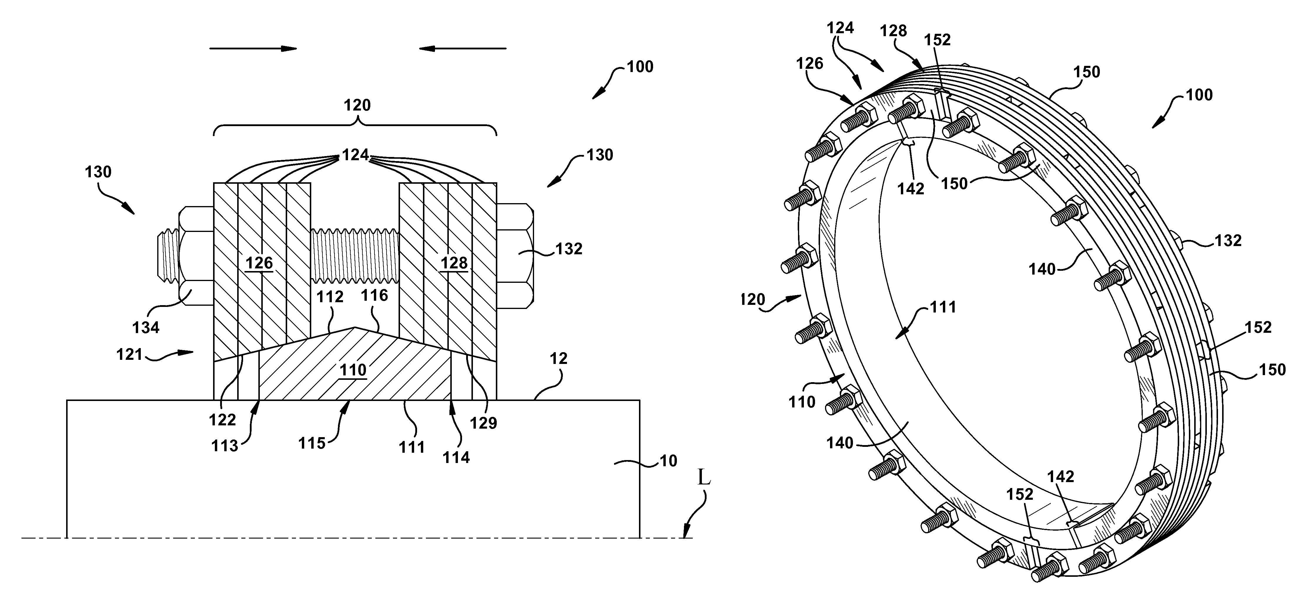
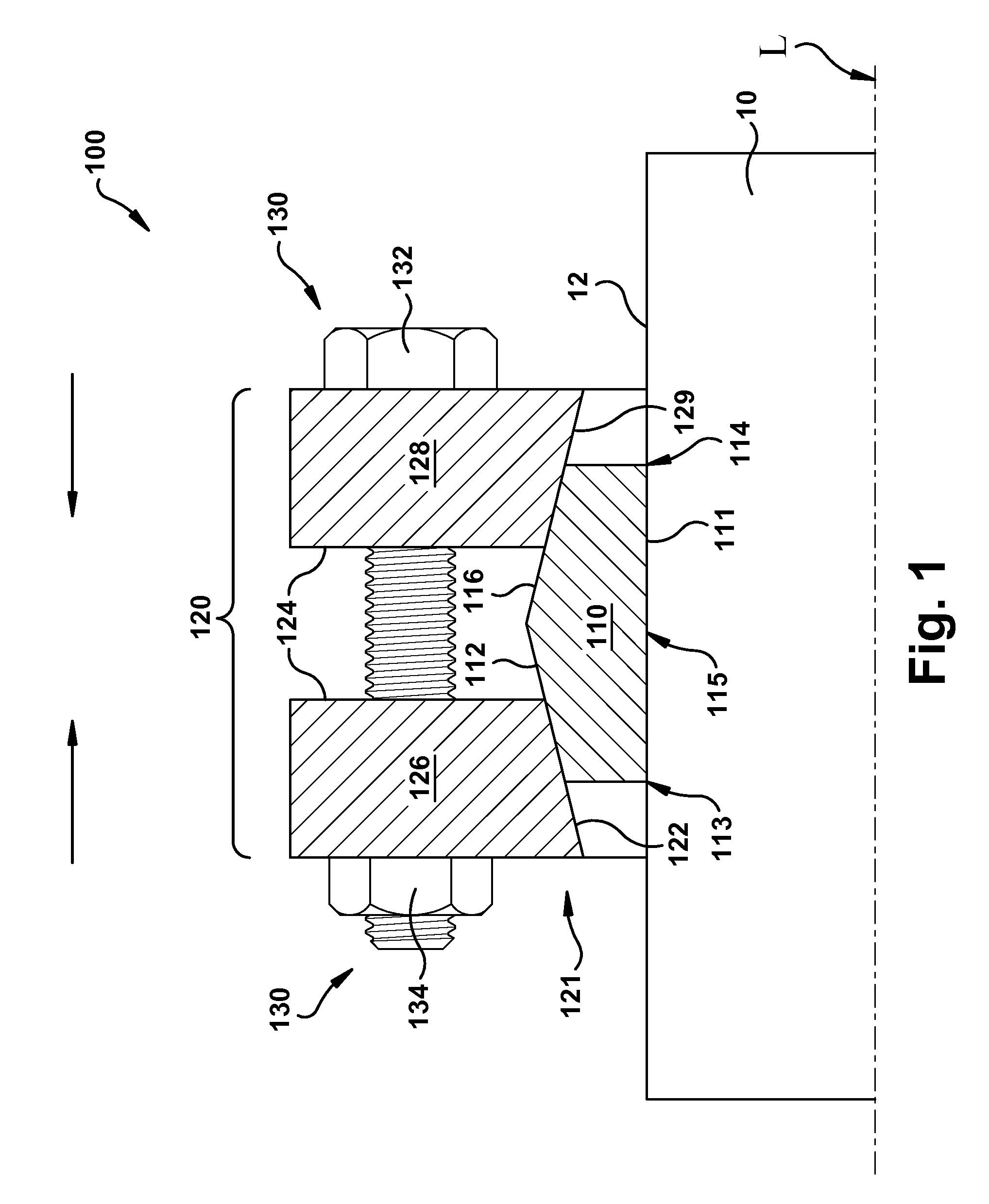
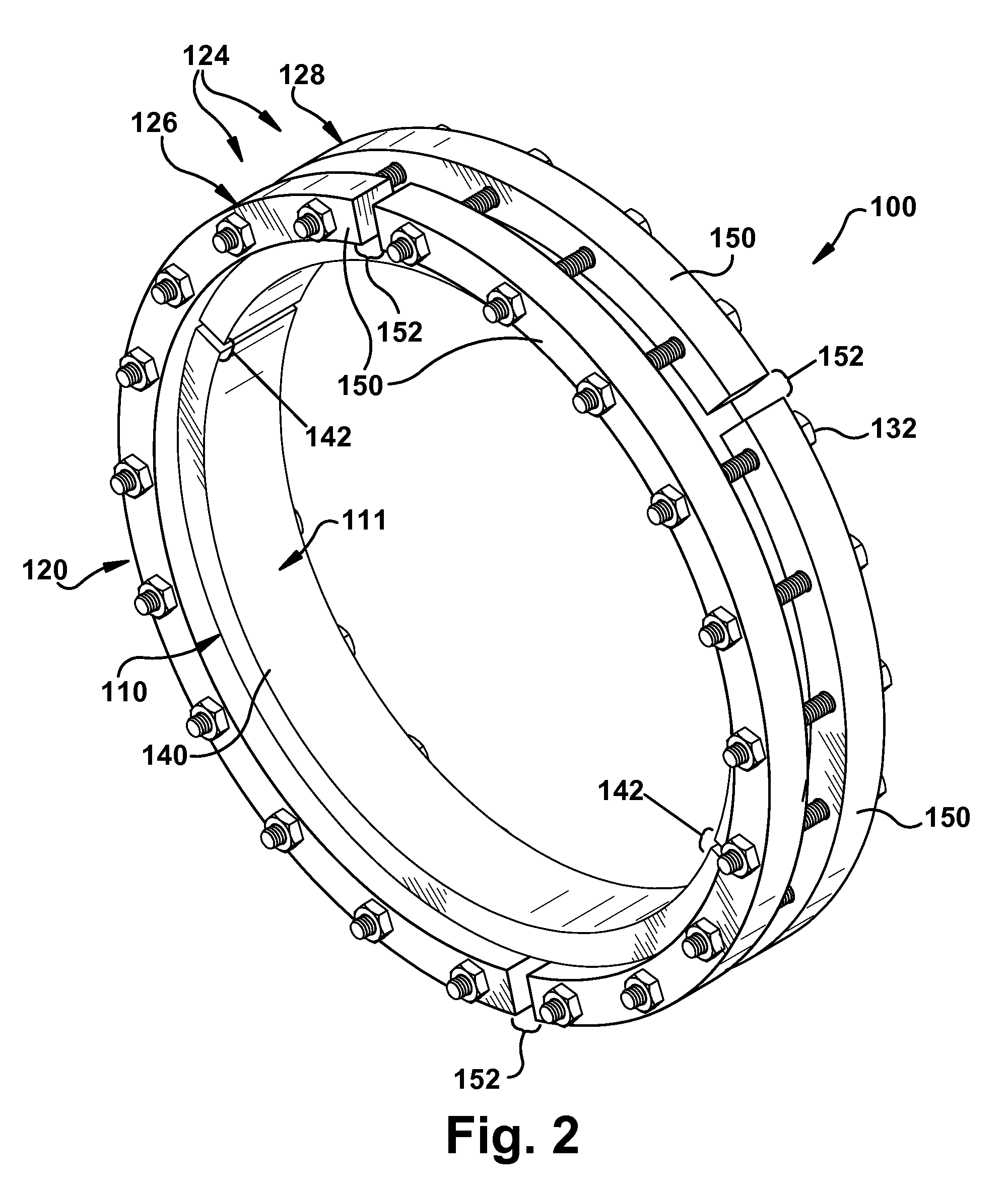
[0020]Aspects of the invention provide a way to add mass to a rotating body, such as a rotor, to change a torsional resonance frequency of the rotor or a respective rotor train without removal of the rotor from its casing or half shell and without removal of coupling bolts. Broadly, a wedge ring may be squeezed onto the rotor by two or more mass or outer or bolt rings, though multiple wedge rings can be used. By segmenting the wedge ring and / or mass rings so that each includes at least two pieces, an interference fit may be produced by pulling the mass rings together about the wedge ring. A particularly advantageous configuration includes circumferentially staggering gaps between bolt ring segments to reduce stress on the mass rings and / or wedge rings and the assembly overall. As the mass rings are drawn together over the wedge ring on a rotor or the like, an inward radial force is created by wedge action that squeezes the wedge onto the rotor, creating an interference fit. The inte...


PUM


Abstract

Engaging inclined surfaces of an inner ring and an outer ring create wedge action inducing an inward radial force as the rings are forced together longitudinally, holding the adjustor on a rotating body. An inner total arcuate length of each ring is smaller than an outer total arcuate length of a respective target body (inner ring for outer ring, rotating body for inner ring). Arcuate segments of each ring can have inner surfaces with radii of curvature equal to or smaller than that of the target body outer surface, and with a total arcuate length smaller than the circumference of the target body's outer surface.

Description

BACKGROUND OF THE INVENTION[0001]The disclosure relates generally to adjustment of a torsional resonance frequency of a rotating body, such as a gas or steam turbine rotor, and more particularly to adjustment of a moment of inertia and / or mass of such a rotating body to tune or adjust such a torsional resonance frequency.[0002]In the operation of rotating machinery, particularly in the operation of power generation turbines, it is sometimes desirable to change a torsional resonance frequency of one or more rotating elements of the machinery to avoid excessive vibration and / or damage and / or failure of the machinery during operation. Current solutions for doing so typically add mass to a rotor or the like by adding a mass ring. However, the process involves removing the rotor from its half shell or casing so that the mass ring can be heated, placed on a desired mounting location on the rotor, and cooled to form a shrink fit of the mass ring on the rotor. The removal of the rotor from ...

Claims


Application Information

Patent Timeline
Patent Type & Authority Patents(United States)
IPC IPC(8): F16F15/315F16F15/34F16F15/32F16F15/30
CPCF16F15/3153F16F15/30F16F15/322F16F15/34
Inventor LUPE, DOUGLAS ARTHURADIS, WILLIAM EDWARDDEALLENBACH, ROBERT EDWARDDEDE, MEHMET MUHITTINKORABIK, ANDRZEJROTHE, NOAH MATTHEW
Owner GE INFRASTRUCTURE TECH INT LLC
Why Eureka
Try Eureka