

Assembly comprising an adapter and a smart card
- Summary
- Abstract
- Description
- Claims
- Application Information
AI Technical Summary
Benefits of technology
Problems solved by technology
Method used
Image

Examples
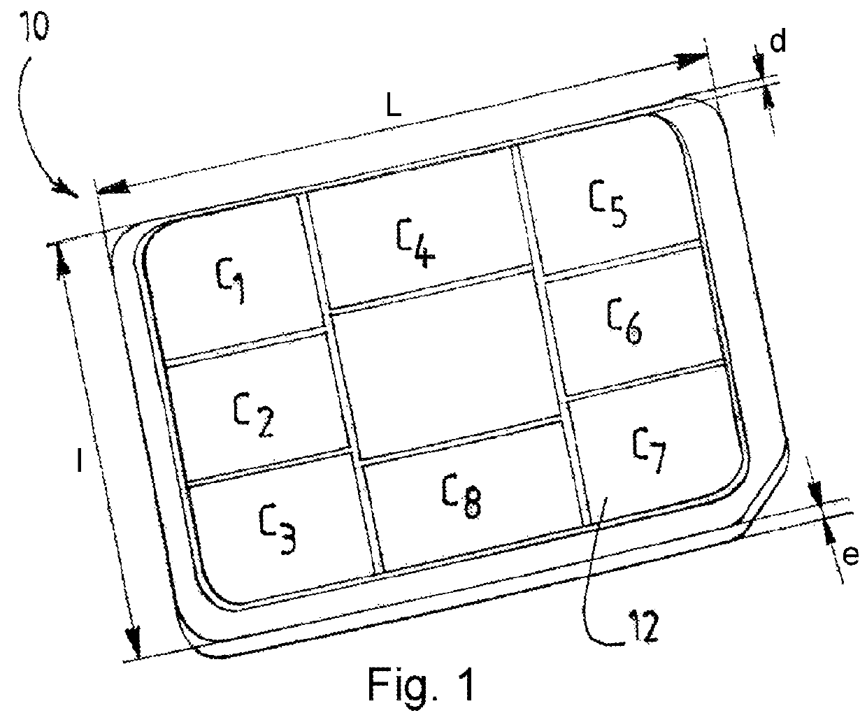
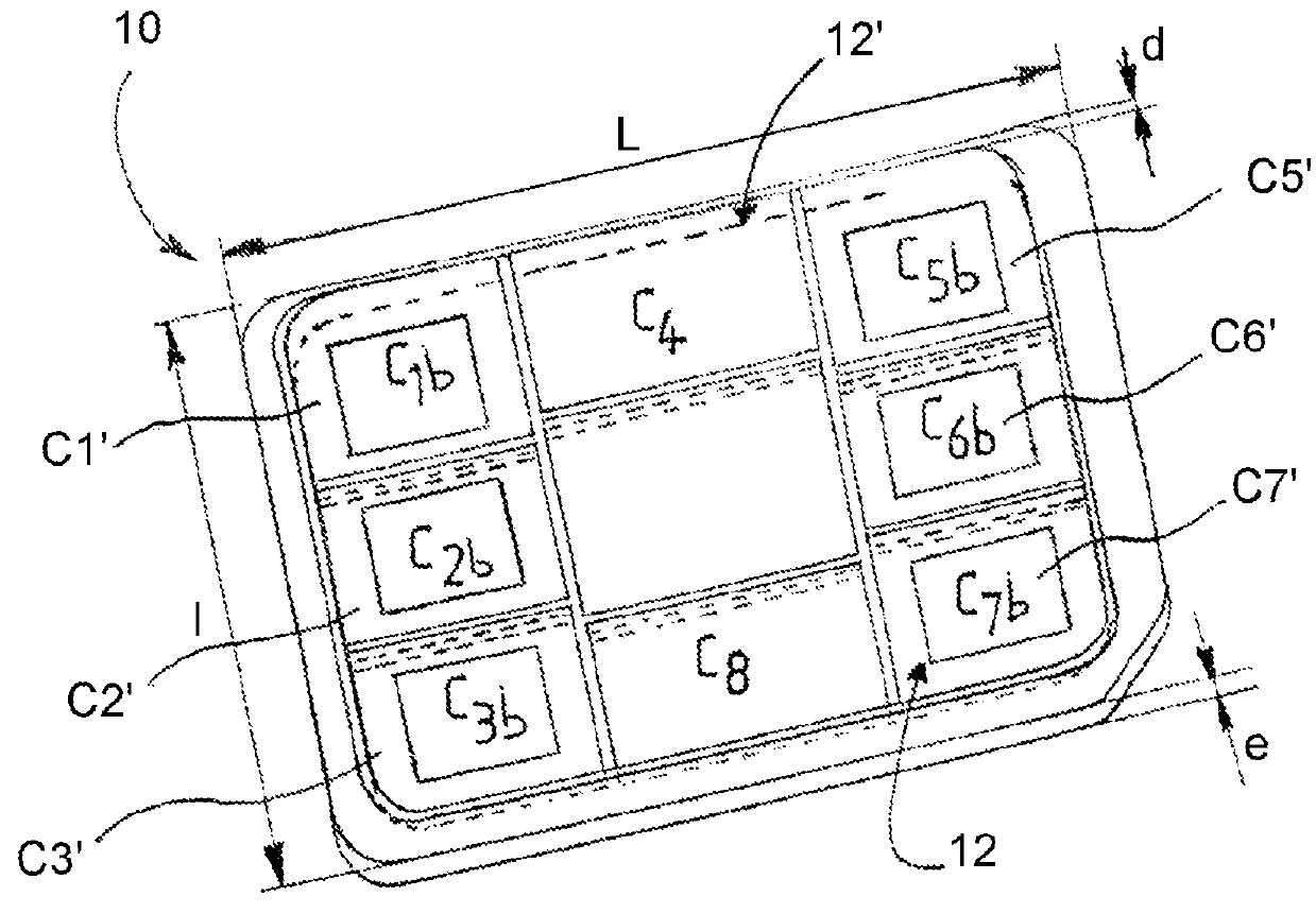
first embodiment
[0071] not shown, the recess of the adapter can be a blind orifice that can comprise a means for holding the smart card. This holding means can be an adhesive element, for example double sided or adhesive transfer, positioned in the bottom of the recess. It is also possible to envision holding the card by inserting the latter into the recess with force, or else by means of a mortise and tenon assembly or by means of any other device that those skilled in the art wish to use and that does not risk being damaged during ordinary use of the adapter and smart card assembly.
[0072]The residual material of the blind orifice, which corresponds to the bottom of the adapter, has a thickness of substantially 60 micrometers (0.76 millimeter corresponding to the average thickness of the card with the 3FF format−0.70 millimeter, which can correspond for example to the maximum thickness of the smart card in a format smaller than the 3FF format).
[0073]The thickness of the bottom can notably depend o...
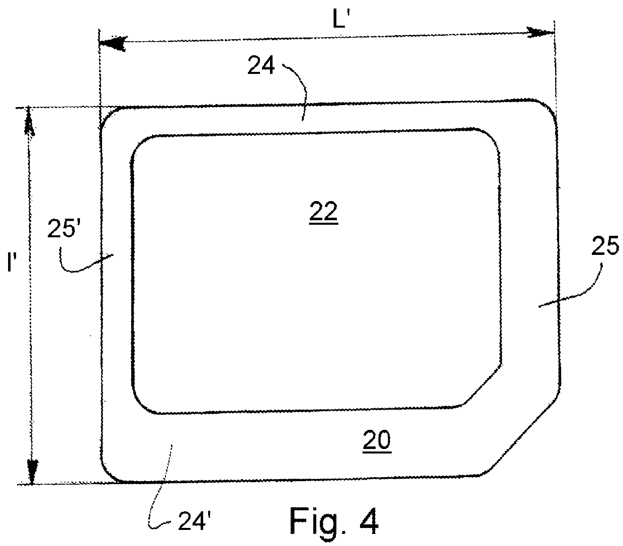
second embodiment
[0075] the recess 22 of the adapter 20 can appear in the form of an outlet opening. The smart card can be made integral with the adapter 20 by at least one holding means.
[0076]In particular, the holding means can be at least one mortise and tenon assembly, the tenon being able to be situated at the card 10 or the adapter 20, the mortise then being on the opposite part.
[0077]The holding means can also be an adhesive element, such as an adhesive film, which then closes up all or part of the orifice 20. The film, adhesive on a single face, can for example cover all or part of the back face of the adapter 20 so that the orifice 22 is at least partly covered by the adhesive. Thus, when the card 10 is positioned in the orifice 22, the adhesive part can hold the card 10 in position in the recess 22.
[0078]It can be envisioned that the adhesive only partly covers the orifice 22 in order to limit the risks of tearing the adhesive film, particularly when one wishes to withdraw the card 10 from...
PUM
 Abstract
Description
Claims
Application Information