Scalable single-stage differential power converter

a power converter and single-stage technology, applied in the field of power conversion, can solve the problems of high number of devices, high complexity of drivers and protection circuits, and inability to accept compact applications with 60-hz line transformers, and achieve the effect of reducing the dc component of steady-state dynamics and reducing the harmonics of higher order

Active Publication Date: 2016-06-28
THE BOARD OF TRUSTEES OF THE UNIV OF ILLINOIS
View PDF6 Cites 4 Cited by
  • Summary
  • Abstract
  • Description
  • Claims
  • Application Information

AI Technical Summary

Benefits of technology

[0010]An embodiment of the invention is a scalable single-stage differential power converter. The converter can be implemented in signal, split and multi-phases (i.e. with two or more phases). In an example embodiment, a three-phase converter can be achieved with only three modules. The concept is also scalable for N-phase (with N>1) converter, which employs N modules. Integrated magnetics used in preferred embodiments of the invention mitigate the DC component of the steady-state dynamics and can be extended to AC ripple mitigation. Control architectures in preferred embodiments can mitigate higher order harmonics in steady-state dynamics. Embodiments of the invention also provide scalability for voltage- and current-source topologies.

Problems solved by technology

The bulky 60-Hz line transformer is not acceptable for compact applications.
However, the HFL converters have limitations.
Generally, the number of devices and the complexity of the drivers and protection circuitry are high in such HFL multi-stage converters.
Further, and as mentioned earlier, some of the high-frequency converters may include intermediate stage high-voltage DC-link electrolytic capacitors that are bulky and have long-term reliability issues.
Control is difficult in these arrangements because each of these multi-stage converters have to be controlled, which raises control complexity and computational burden.
The arrangements are not always readily scalable because topology is often functionality dependent and a generic architecture may come at the price of higher number of devices and associated drive and protection complexities.
These architectures also have more difficult path to achieving desirable efficiency since loss of each stage of the multistage converter has to be controlled via careful and complex design.
However, as mentioned above, the 2008 disclosure by S. K. Mazumder et al. was for an inverter (DC-AC) and not for a DC-DC application and had a differential mode.
While this concept provided a low-circuit-count design, problems with this design related to scalability, noise components, and nonlinear voltage gain, and closed-loop control remained unresolved.
This increases device count and circuit complexity, while reducing efficiency and reliability.
The nonlinearity of the voltage gain of the converter could not be adequately handled with this control, and that control was only demonstrated for the particular circuit and inverter type.

Method used


Image

  • Scalable single-stage differential power converter
  • Scalable single-stage differential power converter
  • Scalable single-stage differential power converter

Examples


Embodiment Construction

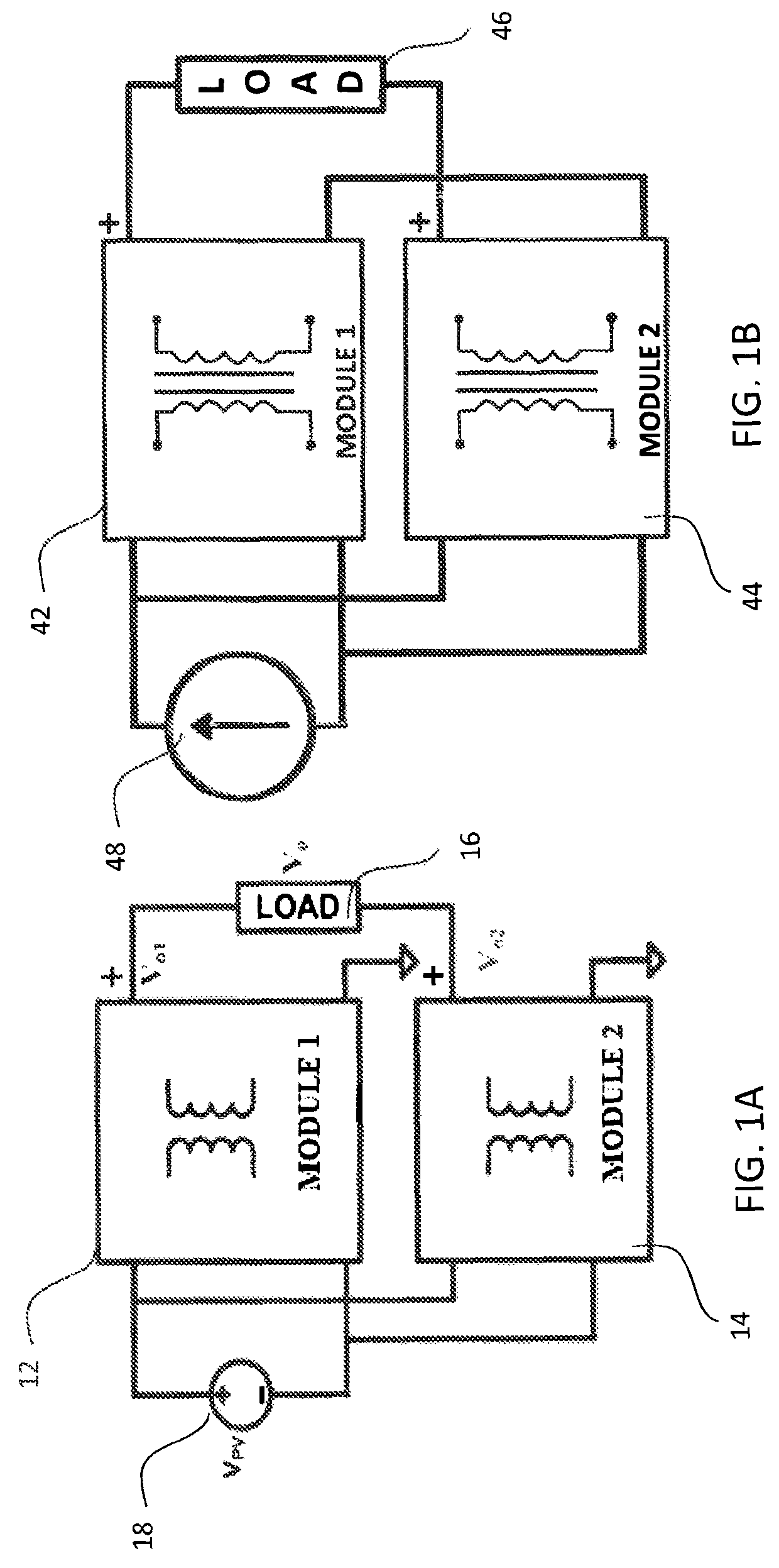
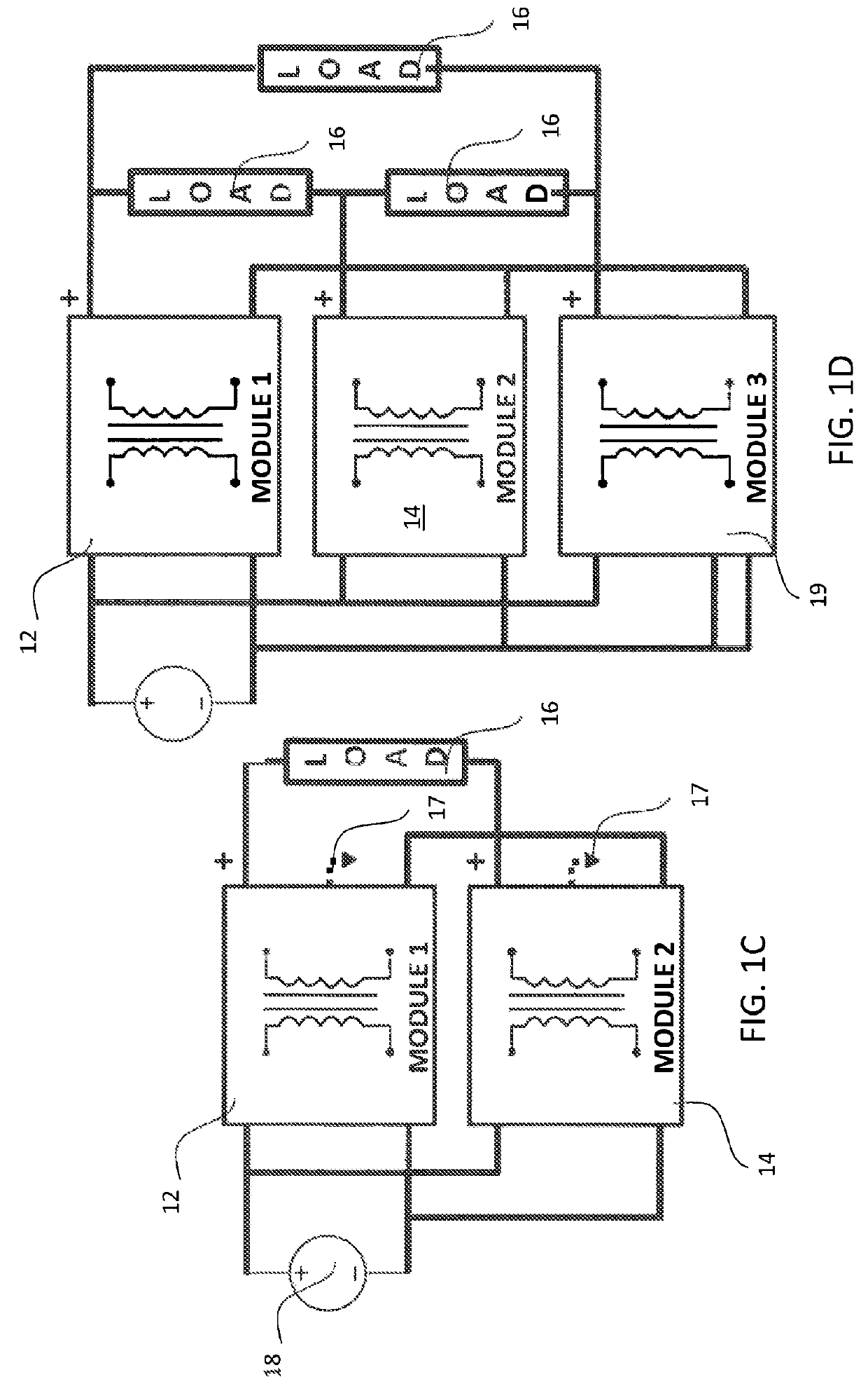
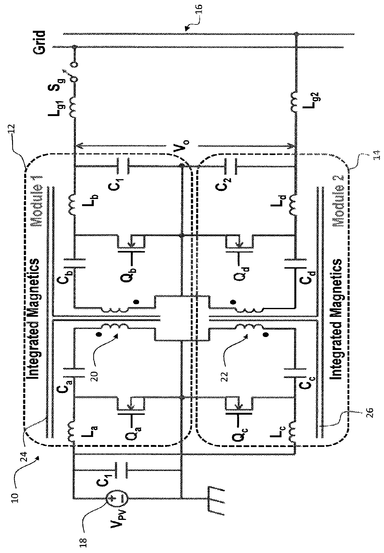
[0021]An embodiment of the invention provides scalable differential power converters. Embodiments of the invention provide applicability for single phase and scalability for both split phase and multiple phases. An N-phase (with N>1) multiphase extension can be achieved with N modules. For instance, an example three-phase application will employ three modules. This reduces complexity by half compared to the Mazumder 2008 paper discussed in the background section. Integrated magnetics can be at module or converter level. Integrated magnetics at the converter level used in embodiments of the invention mitigate the DC component of the steady-state dynamics and can be extended for AC ripple mitigation via incorporation of ripple rejection circuitry. Preferred control architectures of the invention are applicable for single, split-, or multiple phases, can be scalable for linear / nonlinear compensation and stationary / time-invariant frame, and can overcome the nonlinearity of the converter...


PUM


Abstract

An embodiment of the invention is a scalable single stage differential power converter. The inverter can be implemented in signal, split and multi-phases. A multiphase converter can be achieved with only three modules. Integrated magnetics used in preferred embodiments of the invention mitigate the DC component of the steady-state dynamics and can be extended to AC ripple mitigation. Control architectures in preferred embodiments can mitigate higher order harmonics in steady state dynamics. Embodiments of the invention also provide scalability for voltage and current source topologies.

Description

PRIORITY CLAIM AND REFERENCE TO RELATED APPLICATION[0001]The application claims priority under 35 U.S.C. §119 from prior provisional application Ser. No. 61 / 500,344, which was filed Jun. 23, 2011.STATEMENT OF GOVERNMENT INTEREST[0002]This invention was made with Government support under Grant No. 0725887 awarded by the National Science Foundation. The Government has certain rights in the invention.FIELD[0003]A field of the invention is power conversion. Example applications of the invention include conversion of power from solar cells, fuel cells, batteries, wind energy source, grid to voltage levels required by a load or power system, including microgrid applications, electric vehicle applications.BACKGROUND[0004]Leveraging the potential of low power so-called green or renewable power sources such as photovoltaic (solar cells), fuel cells, wind and other such power generation technologies requires efficient and well-behaved converters. The power sources have a DC power output with ...

Claims


Application Information

Patent Timeline
Patent Type & Authority Patents(United States)
IPC IPC(8): H02J1/10H02M7/537H02M7/48H02M3/00H02M1/12
CPCH02M7/537H02M3/005H02M7/48H02M7/4807H02M1/12
Inventor MAZUMDER, SUDIP K.
Owner THE BOARD OF TRUSTEES OF THE UNIV OF ILLINOIS
Why Eureka
Try Eureka