Direct current component control method and system used for three-phase or single-phase inverter

A three-phase inverter, single-phase inverter technology, applied in the direction of converting AC power input to DC power output, output power conversion devices, electrical components, etc., can solve problems such as the defect that the DC component of the output voltage cannot be eliminated.

Active Publication Date: 2015-05-27
BYD CO LTD
View PDF4 Cites 0 Cited by
  • Summary
  • Abstract
  • Description
  • Claims
  • Application Information

AI Technical Summary

Problems solved by technology

[0003] The purpose of the present invention is to at least solve one of the above-mentioned technical defects, especially solve the defect that the DC component in the output voltage cannot be eliminated in the prior art

Method used


Image

  • Direct current component control method and system used for three-phase or single-phase inverter
  • Direct current component control method and system used for three-phase or single-phase inverter
  • Direct current component control method and system used for three-phase or single-phase inverter

Examples


Embodiment 1

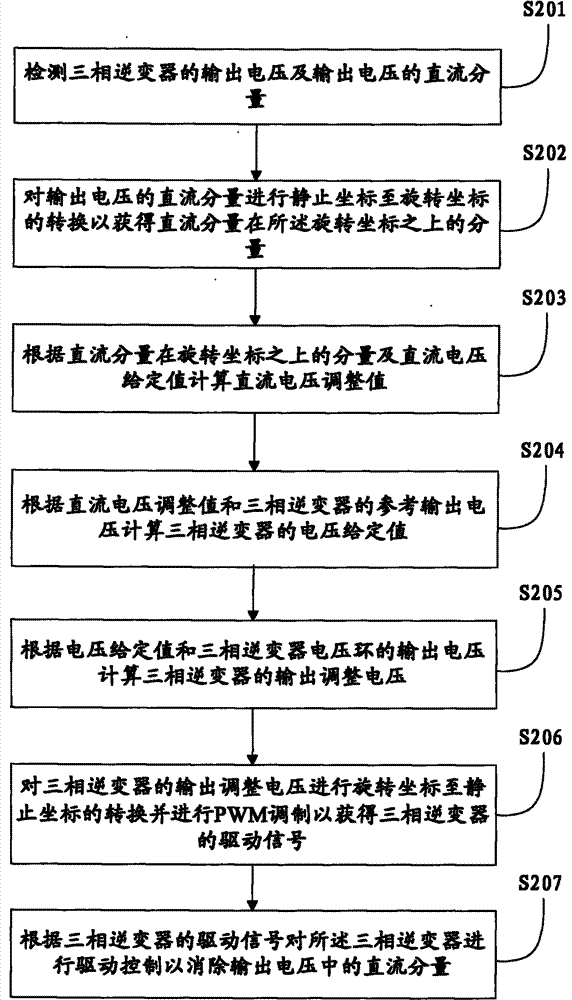
[0024] like figure 2As shown, it is a flow chart of a DC component control method for a three-phase inverter in Embodiment 1 of the present invention, including the following steps:

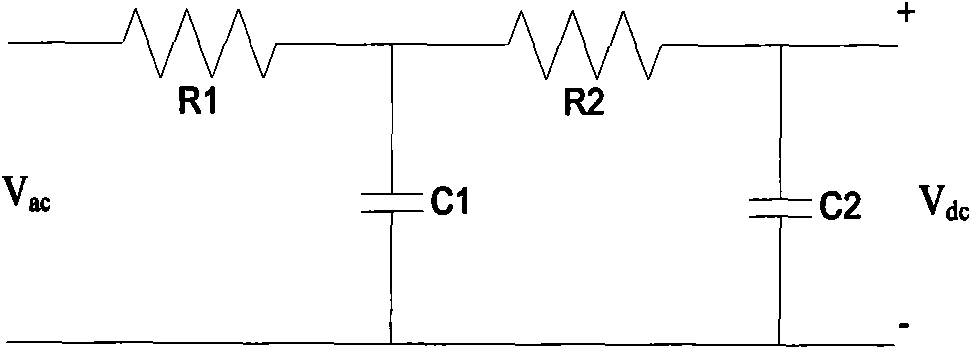
[0025] Step S201, detecting the output voltage of the three-phase inverter and the DC component of the output voltage. Let the detected output voltages of the three-phase inverter be Ua, Ub, and Uc, and the output voltages are Ua, Ub, and Uc to obtain the DC components Uade, Ubde, and Ucdc of the three-phase inverter output voltage through the DC component detection circuit. In one embodiment of the present invention, the DC component of the output voltage of the three-phase inverter is detected by a second-order low-pass filter with a cutoff frequency of about 1 Hz. like image 3 Shown is a schematic diagram of a second-order low-pass filter according to an embodiment of the present invention.

[0026] Step S202, converting the DC components Uadc, Ubdc, and Ucdc of the output voltage from a / ...

Embodiment 2

[0039] like Figure 6 As shown, it is a flowchart of a DC component control method for a single-phase inverter in Embodiment 2 of the present invention, including the following steps:

Embodiment example

[0040] Step S601, constructing the structure of the three-phase inverter according to the structure of the single-phase inverter, and using the single-phase inverter as the first phase of the three-phase inverter. It should be noted that, in the embodiment of the present invention, the single-phase inverter can be used as any phase of the three-phase inverter, which can be A phase, B phase or C phase, so the above-mentioned first phase Can be A phase, B phase or C phase. In the embodiments of the present invention, the single-phase inverter is used as the A-phase as an example for description. Compared with the three-phase inverter, the single-phase inverter lacks the required complete three-phase power supply signal and topology structure, so it is necessary to construct the topology structure of B and C two phases and the corresponding transfer function virtually, so as to meet the requirements of vector control. Requirements for three-phase power supply. As an embodiment ...


PUM


Abstract

The invention provides a direct current component control method and system used for a three-phase or single-phase inverter, wherein the method used for the three-phase inverter comprises the following steps: detecting the output voltage and direct-current component of the three-phase inverter; carrying out conversion from static coordinates to rotational coordinates on the direct current component so as to obtain a component of the direct current component on the rotational coordinates; calculating a direct voltage adjusted value according to the component of the direct current component on the rotational coordinates and a direct current voltage given value, and calculating the voltage given value according to the direct voltage adjusted value and a reference output voltage; calculating the output regulation voltage of the three-phase inverter according to the voltage given value and the output voltage of the three-phase inverter, and carrying out conversion from the rotational coordinates to the static coordinates on the output regulation voltage of the of the three-phase inverter and carrying out PWM (pulse-width modulation) so as to obtain driving signals of the three-phase inverter; and carrying out driving control on the three-phase inverter according to the driving signals. The method and system provided by the invention can be used for effectively reducing the direct-current component in the output voltage of the inverter so as to adapt to load requirements.

Description

technical field [0001] The invention relates to the technical field of electrical manufacturing, in particular to a DC component control method and system for three-phase or single-phase inverters. Background technique [0002] Sine wave inverters are widely used in uninterruptible power supply (UPS), frequency converters and other fields, and the types of loads carried are becoming more and more diverse. This requires that the output of the inverter should be a pure sine wave and should not contain DC components and other components. During the research and practice of the prior art, the inventor found that the DC component of the inverter is unavoidable due to reasons such as BUS voltage imbalance, inaccurate sampling, and deviation of circuit parameters. If effective measures are not taken to suppress it, the DC component in the output voltage may cause harm to the loads it supplies, such as inductive loads such as "magnetic saturation" of transformers, etc., so that the...

Claims


Application Information

Patent Timeline
Patent Type & Authority Patents(China)
IPC IPC(8): H02M7/5387H02M1/14
Inventor 夏田刘宏亮肖力龙
Owner BYD CO LTD
Why Eureka
Try Eureka