Flow cell for radiation detector

a radiation detector and flow cell technology, applied in the field of radiochemistry, can solve the problems of operator waiting, detector re-qualification, problem of achieving such a wide linear range of radio-detectors, etc., and achieve the effect of improving the linear detection range of radio-detectors, simple and cost-effective setting up

Active Publication Date: 2016-07-05
GE HEALTHCARE LTD
View PDF6 Cites 2 Cited by
  • Summary
  • Abstract
  • Description
  • Claims
  • Application Information

AI Technical Summary

Benefits of technology

[0007]In view of the needs of the art, the present invention provides a radio-detector system including a flow cell that can be used to improve the linear detection range of a radio-detector. The flow cell is simple and cost-effective to set up and provides technical advantages over methods known in the prior art. The present invention also provides a method to determine the RCP of a radioactive composition making use of the radio-detector system of the present invention, and a HPLC system incorporating the radio-detector system of the present invention. The invention permits a radio-detector's defined linear range to apply to a wide range of chromatography conditions. Importantly, the invention also allows HPLC methods with different flow rates to be used without affecting the qualification status of radio-detector.

Problems solved by technology

To achieve such a wide linear range for radio-detectors can be problematic.
Such intervention has the disadvantage of requiring detector re-qualification and may require the operator to wait until activity levels within the hot cell containing the detector decay to safe levels.

Method used


Image

  • Flow cell for radiation detector
  • Flow cell for radiation detector
  • Flow cell for radiation detector

Examples


example 1

Manufacture of a Flow Cell

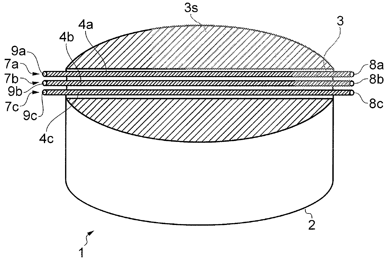
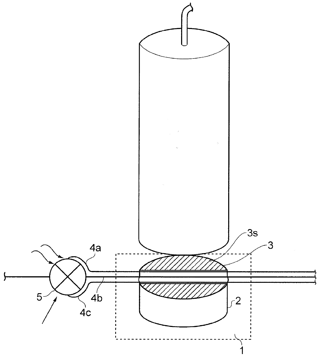
[0074]As illustrated in FIG. 5, a channel 3 was etched into the flat surface of a circular plexiglass block. Three lengths of PEEK tubing were positioned within the channel, with enough tubing to attach to the outflow from the UV detector and enough tubing to reach waste collector. The plexiglass mounting was chosen to protect the surface of the radio-detector crystal from any contact with the tubing as this could damage the crystal.

[0075]The exposed diameter of the crystal (through its lead shielding) was ca. 2 cm. This was taken as the length of each piece of tubing within the detector. However, since the mounting was plexiglass, some of the tubing at the inlet and outlet may have contributed to the signal. Since this is constant for all tubings, the ratio of the cell volumes for the different ID tubing remains constant and interpretation of the results the same. The three tubings were sent individually to the waste container.

example 2

Evaluation of Detector Linearity

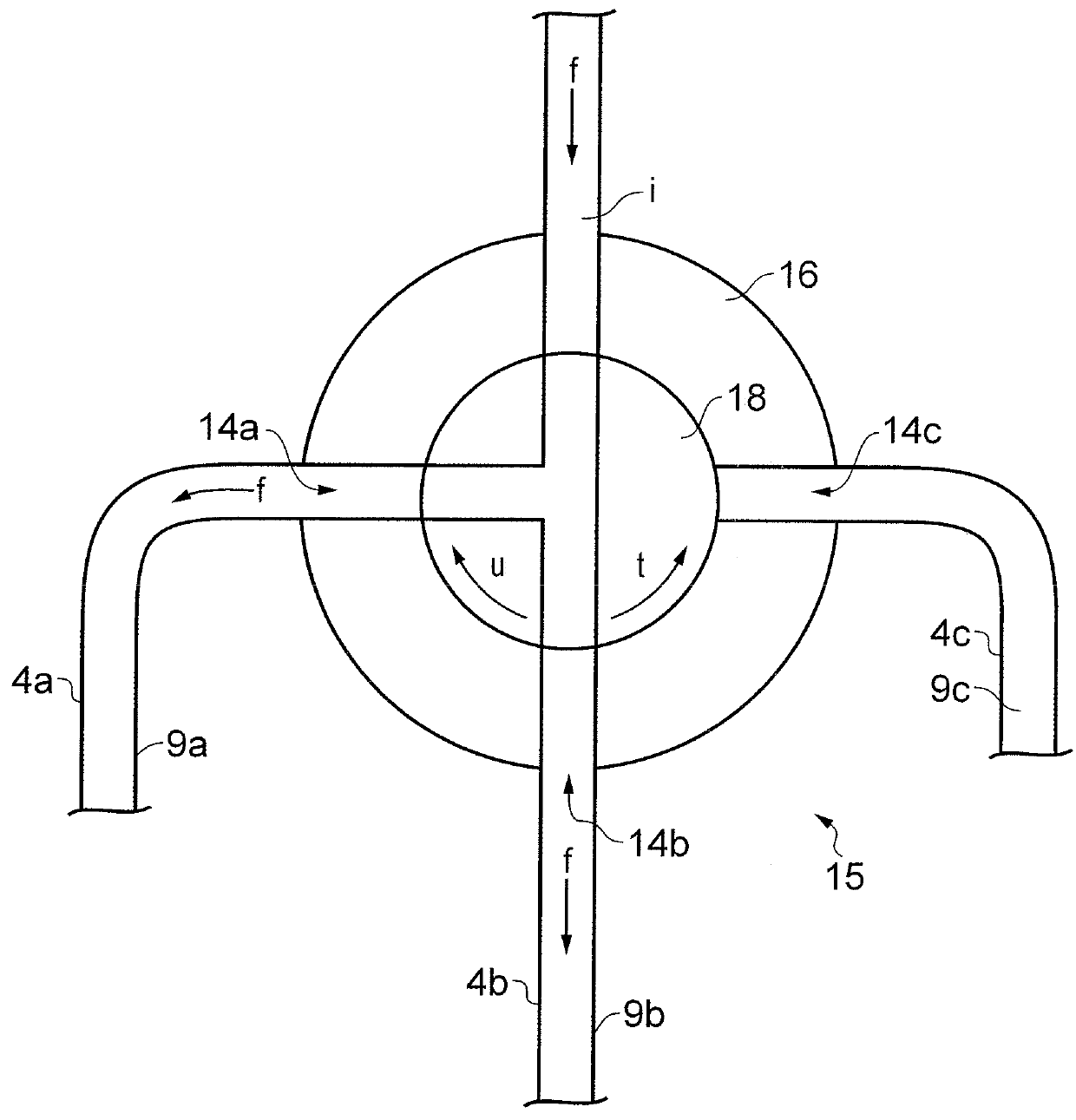
[0076]Investigation of the linearity of the detector was performed by injection of [18F]Fluoride. The largest detector volume (Green PEEK tubing: 9.2 μL) and the smallest detector volume (Red PEEK tubing: 0.25 μL) were studied. The cell volumes were switched manually by simply switching the inlet tubing. This could be automated (and operated within a chromatography data system, such as Chromeleon) by using a switching valve. The plot (FIG. 6) shows how the detector slope is directly proportional to the flow cell volume.

example 3

Evaluation of Detector Sensitivity

[0077]For detector sensitivity, a preparation of the PET tracer 18F-flutametamol (prepared according to the method set out by Nelissen et al 2009 J Nuc Med; 50(8): 1251-1259) was analysed. The injection volume was altered so that the on-column activity was the same for all three detector volumes studied. Injection volumes were 20, 25 and 35 μL for RED (0.25 μl PEEK tubing), ORANGE (4.0 μl PEEK tubing) and GREEN (9.2 μl PEEK tubing) tubings, respectively (in that order). The volumes were adjusted, allowing for sample decay, to ensure that approximately the same on column activity was analysed. The total radiodetector signal (total peak areas) was found to be directly proportional to the flow cell volume (FIG. 7a). The sensitivity of the radiodetector for the detection of radio impurities was improved as the radiodetector volume was increased (FIG. 7b).


PUM

PropertyMeasurementUnit
flow rateaaaaaaaaaa
volumeaaaaaaaaaa
volumeaaaaaaaaaa

Abstract

The present invention provides a flow cell that can be used to improve the linear detection range of a radio-detector. The flow cell of the present invention is simple and cost-effective to set up and provides technical advantages over methods known in the prior art, as set out in more detail hereunder. The present invention also provides a method to determine the RCP of a radioactive composition making use of said flow cell, and a HPLC system comprising said flow cell.

Description

[0001]This application is a filing under 35 U.S.C. 371 of international application number PCT / EP2012 / 069346, filed Oct. 1, 2012, published on Apr. 4, 2013 as WO 2013 / 045697, which claims priority to U.S. provisional patent application No. 61 / 541,107 filed Sep. 30, 2011 and to application number 1116859.8 filed in Great Britain on Sep. 30, 2011.TECHNICAL FIELD OF THE INVENTION[0002]The present invention concerns the field of radiochemistry and in particular the determination of the radiochemical purity (RCP) of a radiochemical composition. More specifically, the present invention relates to optimising the linear range of the radio-detector used for the determination of RCP.DESCRIPTION OF RELATED ART[0003]Synthetic procedures to obtain radiolabelled compounds involve reaction of a suitable chemical form of a radionuclide with a precursor compound. The desired radiolabelled compound is usually obtained in addition to other chemical and radiochemical compounds that can be regarded as i...

Claims


Application Information

Patent Timeline
Patent Type & Authority Patents(United States)
IPC IPC(8): G01T1/20G01T7/02G01N30/62G01N21/00G01T1/00G01N30/00
CPCG01T1/2006G01N30/62G01T1/003G01T7/02G01N2030/77
Inventor CLARKE, ALAN PETERRAJANAYAGAM, THANUSHANPETTITT, ROGER PAULCHISHOLM, ROBERT F.
Owner GE HEALTHCARE LTD
Why Eureka
Try Eureka