Traffic engineering for large scale data center networks

a data center network and traffic engineering technology, applied in the field of traffic engineering for large data center networks, can solve the problems of increasing the overall size of the data center, challenging to provide a system with fair bandwidth, and especially challenging

Active Publication Date: 2016-07-19
GOOGLE LLC
View PDF7 Cites 0 Cited by
  • Summary
  • Abstract
  • Description
  • Claims
  • Application Information

AI Technical Summary

Benefits of technology

[0005]In one alternative, the method further comprises generating a route computation graph that facilitates bandwidth allocation through iterative selection of source and destination middle blocks maximizing the condition. In another alternative, the method further comprises, for each source fabric block, splitting demand to a destination fabric block equally among each non-faulty middle block in the destination fabric block.

Problems solved by technology

However, it is challenging to provide a system with fair bandwidth allocation that also respects different classes of service, and that efficiently works across the multi-level switching environment.
This can be especially challenging as the number of hosts and the overall size of the data center increase.

Method used


Image

  • Traffic engineering for large scale data center networks
  • Traffic engineering for large scale data center networks
  • Traffic engineering for large scale data center networks

Examples


Embodiment Construction

[0019]Aspects, features and advantages of the disclosure will be appreciated when considered with reference to the following description of embodiments and accompanying figures. The same reference numbers in different drawings may identify the same or similar elements. Furthermore, the following description is not limiting; the scope of the present technology is defined by the appended claims and equivalents. While certain processes in accordance with example embodiments are shown in the figures as occurring in a linear fashion, this is not a requirement unless expressly stated herein. Different processes may be performed in a different order or concurrently. Steps may also be added or omitted unless otherwise stated.

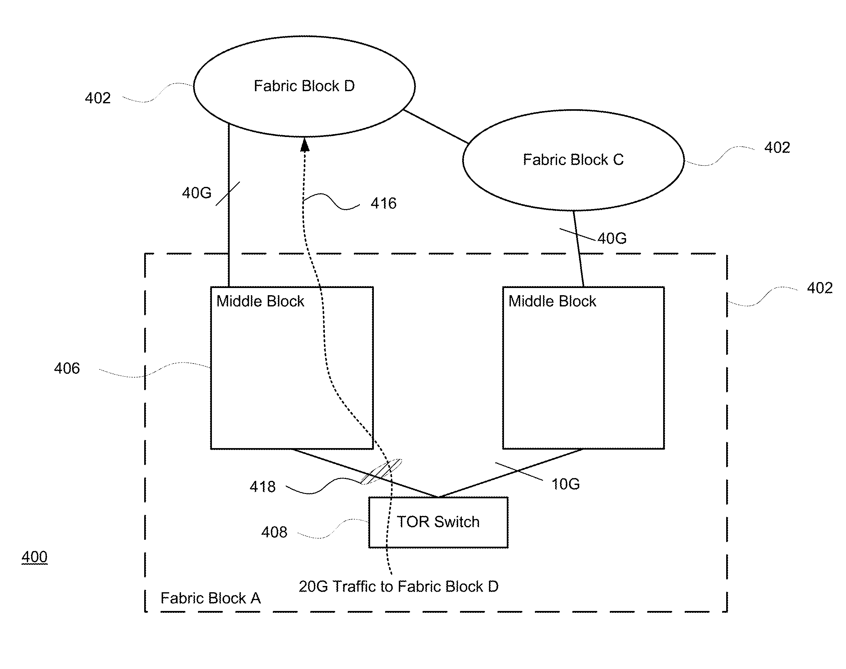
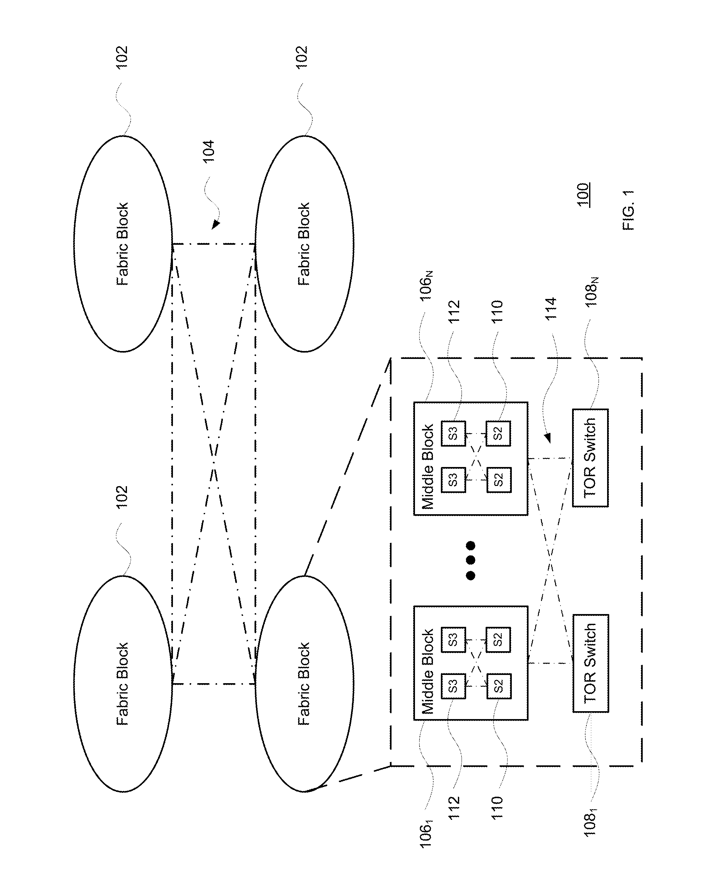
[0020]The technology described herein presents a traffic engineering solution for data center networks, including networks employing direct connect topologies. As noted above, large scale data center networks may include multiple stages of switches that incorporate trad...


PUM


Abstract

The present disclosure provides for the determination of bandwidth allocation of inter-block traffic in a data center network. It employs a number of optimization objectives and a heuristic water-filling strategy to avoid producing unnecessary paths and to avoid determining paths that would be unavailable when actually needed. Allocation may be adjusted incrementally upon node and link failure, for instance to perform only the minimal allocation changes necessary. If demand between a source and a destination cannot be satisfied, a decomposition process may be used to allocate remaining demand. One aspect constructs a graph for route computation based on inter-block topology. Here, the graph initially starts with a highest level of abstraction with each node representing a middle block, and gradually reduces the abstraction level to identify paths of mixed abstraction level to satisfy additional demand.

Description

BACKGROUND[0001]In computer data centers, many different hosts are used to process, store and transfer large amounts of data. Each host may include one or more processors, memories and interfaces. The hosts, such as servers, are often arranged within racks, with multiple servers housed per rack. Each rack may have a top-of-rack (“TOR”) switch for communication with a next switching layer. This switching layer may include a cluster of switches (“middle blocks”) that provides bisectional high volume localized traffic. In turn, multiple middle blocks may be logically grouped into larger clusters (“fabric blocks”). This creates a multi-level switching arrangement.[0002]Fabric blocks can be located across the data center, with their highest stage of switches interconnected using expensive long-range fibers and optics. The interconnections among fabric blocks often employ a direct connection instead of using a CLOS-type topology as a tradeoff between bisectional bandwidth and lower cost. ...

Claims


Application Information

Patent Timeline
Patent Type & Authority Patents(United States)
IPC IPC(8): H04L12/801H04L12/931H04L12/803H04L12/729H04L45/122H04L45/125H04L47/724
CPCH04L49/356H04L49/205H04L47/10H04L45/125H04L47/125
Inventor SHRAER, ALEXANDERZHOU, JUNLANVAHDAT, AMIN
Owner GOOGLE LLC
Why Eureka
Try Eureka