Method and magnetic resonance apparatus for determination of patient movement during data acquisition

a technology of magnetic resonance apparatus and data acquisition, which is applied in the field of method and magnetic resonance apparatus for determining the movement of patients during data acquisition, can solve the problems of high cost expenditure and significant image quality limitations, and achieve the effects of less measurement and calculation time, and increased measurement and calculation tim

Active Publication Date: 2016-08-02
SIEMENS HEALTHCARE GMBH
View PDF11 Cites 1 Cited by
  • Summary
  • Abstract
  • Description
  • Claims
  • Application Information

AI Technical Summary

Benefits of technology

[0017]An object of the present invention is to provide a method for determination of a movement of a subject to be examined during the acquisition of measurement data of a magnetic resonance data set that requires less measurement and calculation time and that can be used in many measurement sequences. Furthermore, it is the object of an invention to provide an MR apparatus with which a movement of a subject to be examined during the acquisition of measurement data of a magnetic resonance data set can be detected with simultaneously a smaller measurement and calculation time increase and with more versatile usability.
[0019]In the inventive method, the strength of the navigator signal is measured in relation to the spatial position of the various antenna elements. In contrast to conventional methods in which a section of a k-space matrix is scanned with a navigator signal and the amplitude and phase values resulting from this are evaluated, according to the invention the navigator signal can merely be evaluated with regard to its signal strength, such that the acquisition of the navigator signal can ensue in a relatively fast and simple manner. The relatively small data set (data quantity) of the navigator signal that is necessary for the determination of the movement of an examination subject according to the inventive method allows an efficient and fast calculation of the movement parameters so that the measurement sequence is only insignificantly limited in terms of its performance. The acquisition of the navigator signal can be implemented within 10 ms or less (such as, for example, within 5 ms or less), in any case within less than 100 ms, such that the measurement time of the sequence is only insignificantly influenced.
[0020]The respective spatial sensitivity profiles of the at least two antenna elements are advantageously taken into account in the determination of the movement of the examination subject. The determination of the movement of the examination subject can thereby ensue more precisely.
[0022]The navigator signals are preferably acquired without radiation of gradient fields. Such an implemented acquisition can be integrated without problems into known measurement sequences, since no gradient fields need to be switched for acquisition of the navigator signals, that would otherwise have to be matched with other gradient fields that are switched during the measurement sequence. The navigator signal acquisition thus can ensue with a very good signal-to-noise ratio.
[0023]In an advantageous embodiment, the position of the nuclear spins excited to resonance in the examination subject by the excitation pulse relative to the spatial position of the antenna elements is additionally taken into account in the determination of movement of the examination subject. It is also then possible to detect movement in a correct manner when the MR examination follows no standard protocol in which, for example, the position of an excited volume (for example a slice) is known in advance in comparison to the spatial position of the at least two antenna elements, and the determination of the movement of the examination subject has been matched with (referenced to) this. In this embodiment the orientation of a slice can now also be arbitrarily selected, for example, and the determination of the movement of the examination subject can be flexibly matched therewith.

Problems solved by technology

Due to its relatively long measurement time, the MR imaging is movement-sensitive, meaning that movement of the examination subject during the acquisition of the measurement data can contribute to significant limitations in the image quality.
Such methods require additional hardware and thus incur a high cost expenditure, so that such methods are not typically used.

Method used


Image

  • Method and magnetic resonance apparatus for determination of patient movement during data acquisition
  • Method and magnetic resonance apparatus for determination of patient movement during data acquisition
  • Method and magnetic resonance apparatus for determination of patient movement during data acquisition

Examples


Embodiment Construction

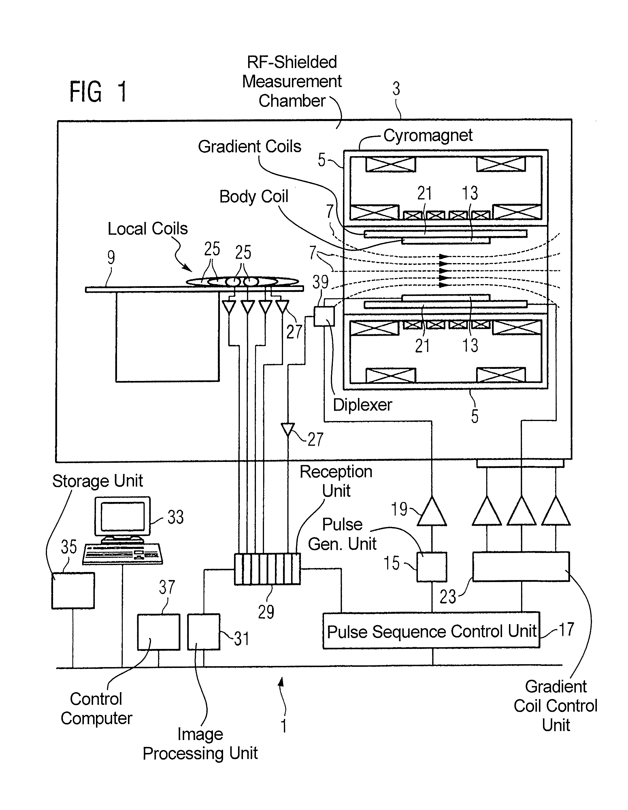
[0031]FIG. 1 schematically shows the basic components of a magnetic resonance apparatus 1. In order to examine a body by means of magnetic resonance imaging, various magnetic fields matched as precisely as possible with one another in terms of their temporal and spatial characteristics are applied.

[0032]A strong magnet (typically a cryomagnet 5 with a tunnel-shaped opening) arranged in a radio-frequency-shielded measurement chamber 3 generates a static, strong basic magnetic field 7 that is typically 0.2 Tesla to 3 Tesla and more. A body or a body pat to be examined (not shown here) is supported on a patient bed 9 and positioned in a homogeneous region of the basic magnetic field 7.

[0033]The excitation of the nuclear spins of the body ensues by radio-frequency excitation pulses that are radiated from a radio-frequency antenna (shown here as a body coil 13). The electrical signals representing radio-frequency excitation pulses are generated by a pulse generation unit 15 that is contr...


PUM


Abstract

In a method and magnetic resonance (MR) apparatus for determination of movement of an examination subject during the acquisition of (MR) measurement data using at least two antenna elements that exhibit respectively different spatial positions, after each radiated excitation pulse a navigator signal is acquired in the measurement data and movement of the examination subject between two excitation pulses during the acquisition of the measurement data is determined from a change of the signal strength of the navigator signal in the at least two antenna elements and based on the respective spatial positions of the antenna elements.

Description

RELATED APPLICATION[0001]The present invention claims the benefit of the filing date of provisional application 60 / 861,202, filed Nov. 22, 2006.BACKGROUND OF THE INVENTION[0002]1. Field of the Invention[0003]The present invention concerns a method for determination of movement by an examination subject during the acquisition of magnetic resonance measurement data. Furthermore, the invention concerns a magnetic resonance apparatus that implements such a method.[0004]2. Description of the Prior Art[0005]Magnetic resonance (MR) technology is a known modality with which images of the inside of an examination subject can be generated. For this purpose, the examination subject is positioned in a strong, static, homogeneous basic magnetic field (field strengths of 0.2 Tesla to 7 Tesla and more) in an MR apparatus such that nuclear spins in the subject orient along the basic magnetic field. Radio-frequency excitation pulses are radiated into the examination subject to trigger nuclear magnet...

Claims


Application Information

Patent Timeline
Patent Type & Authority Patents(United States)
IPC IPC(8): A61B5/11A61B5/00A61B5/055G01R33/567G01R33/565G01R33/3415
CPCA61B5/055A61B5/7207G01R33/3415G01R33/56509G01R33/5673G01R33/5676A61B5/11
Inventor KRUEGER, GUNNARLITTMANN, ARNE
Owner SIEMENS HEALTHCARE GMBH
Why Eureka
Try Eureka