Rectangular thin panel conveyance unit

a technology of conveyance unit and rectangular thin panel, which is applied in the direction of transportation and packaging, packaging goods type, containers, etc., can solve the problems of rectangular thin panel breakage, damage or breakage of rectangular thin panel during conveyance, etc., and achieve the effect of not cracking

Active Publication Date: 2016-08-09
KYORAKU CO LTD
View PDF18 Cites 0 Cited by
  • Summary
  • Abstract
  • Description
  • Claims
  • Application Information

AI Technical Summary

Benefits of technology

[0007]In view of the technical problem described above, it is an object of the present invention to provide a rectangular thin panel conveyance unit that surely prevents damage or breakage of a plurality of rectangular thin panels while conveying the plurality of rectangular thin panels that are stacked so as not to contact one another.Solutions to the Problems

Problems solved by technology

However, as for this module, in the case where the rectangular thin panel is conveyed with a pallet in a state where each of the four corners of the rectangular thin panel without the outer frame is placed on the support surface of this module, the following technical problem arises.
The rectangular thin panel is at risk of damage or breakage during conveyance.
This vibration or collision with support portions above and below may cause damage of the rectangular thin panel and may lead to breakage of the rectangular thin panel in some cases.

Method used


Image

  • Rectangular thin panel conveyance unit
  • Rectangular thin panel conveyance unit
  • Rectangular thin panel conveyance unit

Examples


Embodiment Construction

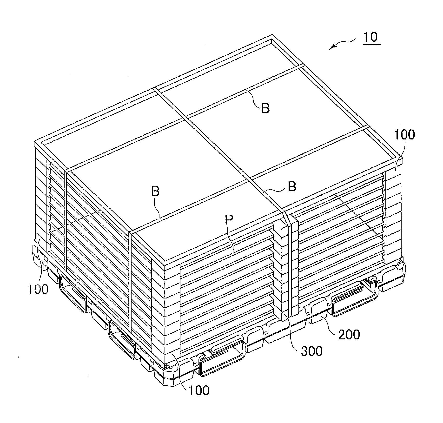
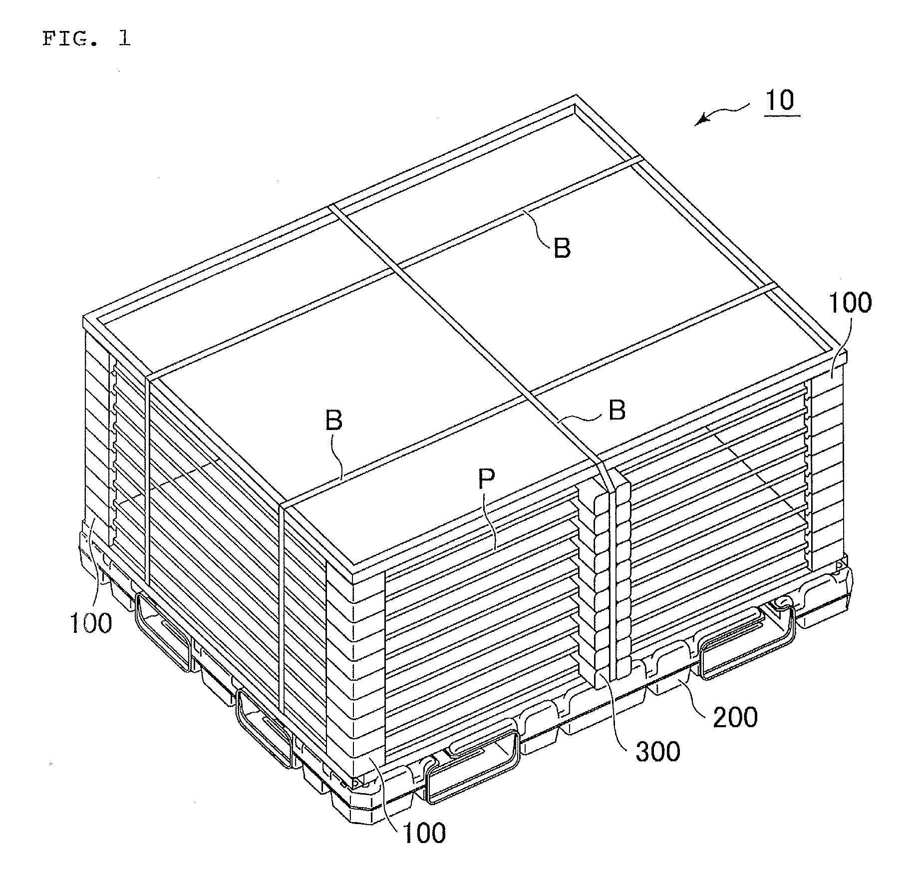
[0027]With an example of the solar panels P as the stacked rectangular thin panels, a thin panel conveyance unit according to an embodiment of the present invention will be described in detail below with reference to the accompanying drawings. The solar panel P includes series-connected cells and is in a form of a thin plate, which is protected by resin, reinforced glass, and a metal frame. More specifically, the solar panel P has a laminated structure where the cell made of silicon is implanted between a glass layer and a plastic layer, or between glass layers. The solar panel P has the thickness of few millimeters, the area of a few square meters, and the weight of 10 to 30 kg. Thus, the solar panel P has a precise and fragile structure.

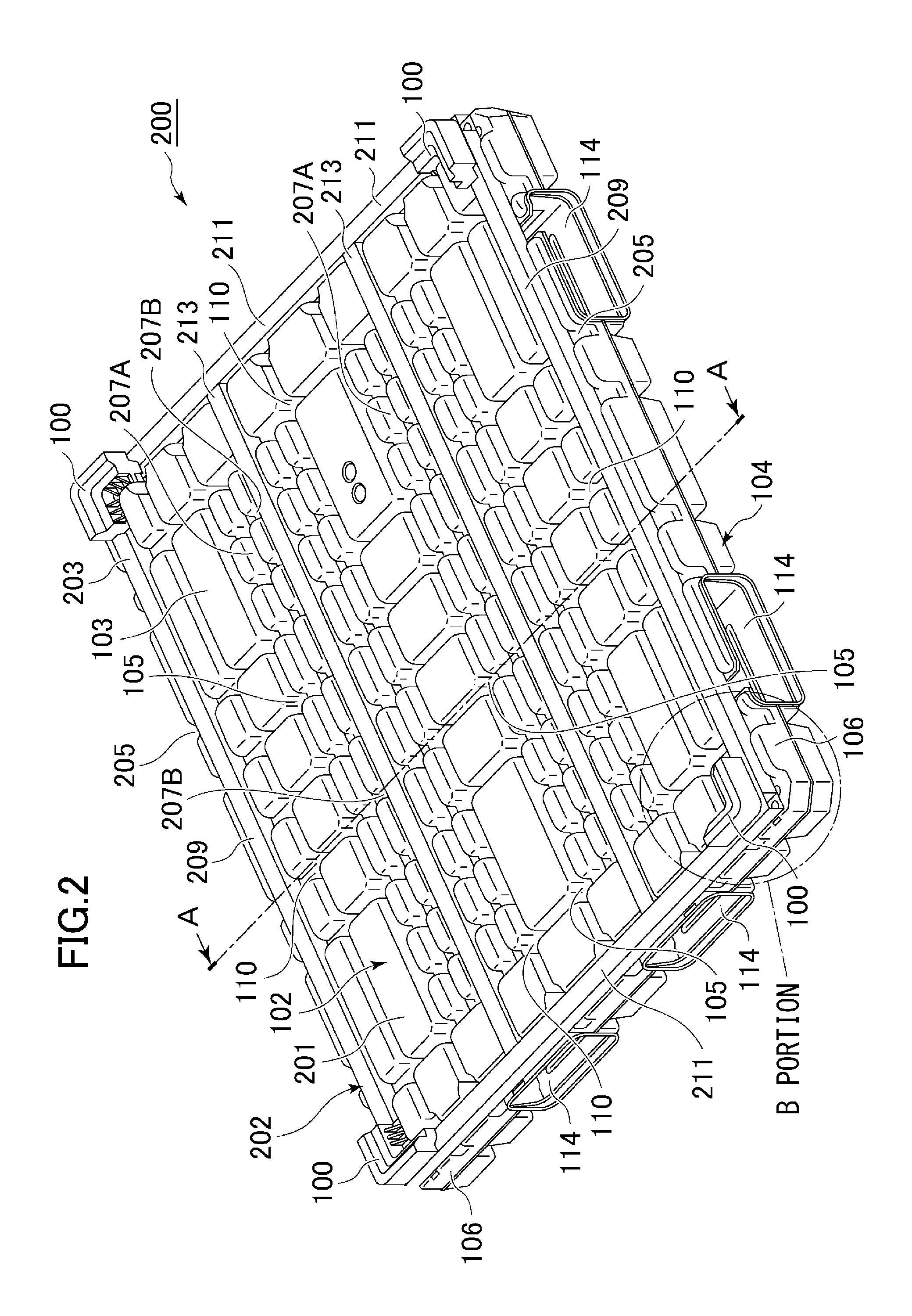
[0028]In this embodiment, a description will be given on the case where the respective four corners of the solar panel P are directly supported by a resin-made corner module. As illustrated in FIG. 1 and FIG. 2, a conveyance unit 10 for the solar p...


PUM

PropertyMeasurementUnit
weightaaaaaaaaaa
thicknessaaaaaaaaaa
widthaaaaaaaaaa

Abstract

A rectangular thin panel conveyance unit includes a plurality of sets of four corner modules, and vibration suppressing bodies for rectangular thin panels in a fixed shape. The corner module has a support surface to support each corner portion of the rectangular thin panel from a lower side. At each corner portion, stacking the corner modules in a vertical direction stacks a plurality of rectangular thin panels in the vertical direction. The vibration suppressing bodies have a thickness equal to or less than the distance between the support surfaces of the corner modules vertically adjacent to one another; and are disposed on each of a top surface and an inferior surface of the rectangular thin panel such that the vibration suppressing body faces a planar portion of each rectangular thin panel to restrict vertical amplitude of vibration of the rectangular thin panel within a predetermined range.

Description

CROSS-REFERENCE TO RELATED APPLICATIONS[0001]The present patent application is a nationalization of International application No. PCT / JP2011 / 006644, filed Nov. 29, 2011, which is based on, and claims priority from, Japanese Application No. 2010-265836, filed Nov. 29, 2010, both of which are incorporated herein by reference in their entireties.TECHNICAL FIELD[0002]The present invention relates to a rectangular thin panel conveyance unit. More specifically, the present invention relates to a rectangular thin panel conveyance unit that surely prevents damage or breakage of a plurality of rectangular thin panels while conveying the plurality of rectangular thin panels that are stacked so as not to contact one another.BACKGROUND ART[0003]Conventionally, a module for storing and conveying fragile and heavy rectangular thin panels such as solar panels that are stacked in the vertical direction so as not to contact one another has been used. Patent Document 1 discloses an example of this mo...

Claims


Application Information

Patent Timeline
Patent Type & Authority Patents(United States)
IPC IPC(8): B65D85/48H01L31/02B65D19/00B65D71/00B65D57/00B65D81/05B65D81/107
CPCB65D19/0036H01L31/02B65D85/48B65D71/0096B65D81/057B65D81/107B65D57/00B65D2519/00278B65D2519/00288B65D2519/00318B65D2519/00815B65D2571/00074B65D2571/00117B65D2519/00034B65D2519/00069B65D2519/00129B65D2519/00273B65D2519/00348B65D2519/00437B65D2519/00562B65D2519/0081B65D2571/00043B65D57/004
Inventor SUEOKA, MASAAKIYAMAUCHI, YOSHIO
Owner KYORAKU CO LTD
Why Eureka
Try Eureka