Actuator, light scanner, image display device, and head mount display
a technology of image display device and light scanner, which is applied in the direction of optics, instruments, optics, etc., can solve the problems of degrading the speed of the light reflecting member disposed on the surface of the attachment section, and achieve the effect of reducing the speed of the light reflecting member
- Summary
- Abstract
- Description
- Claims
- Application Information
AI Technical Summary
Benefits of technology
Problems solved by technology
Method used
Image
Examples
first embodiment
Configuration of Actuator (Light Scanner)
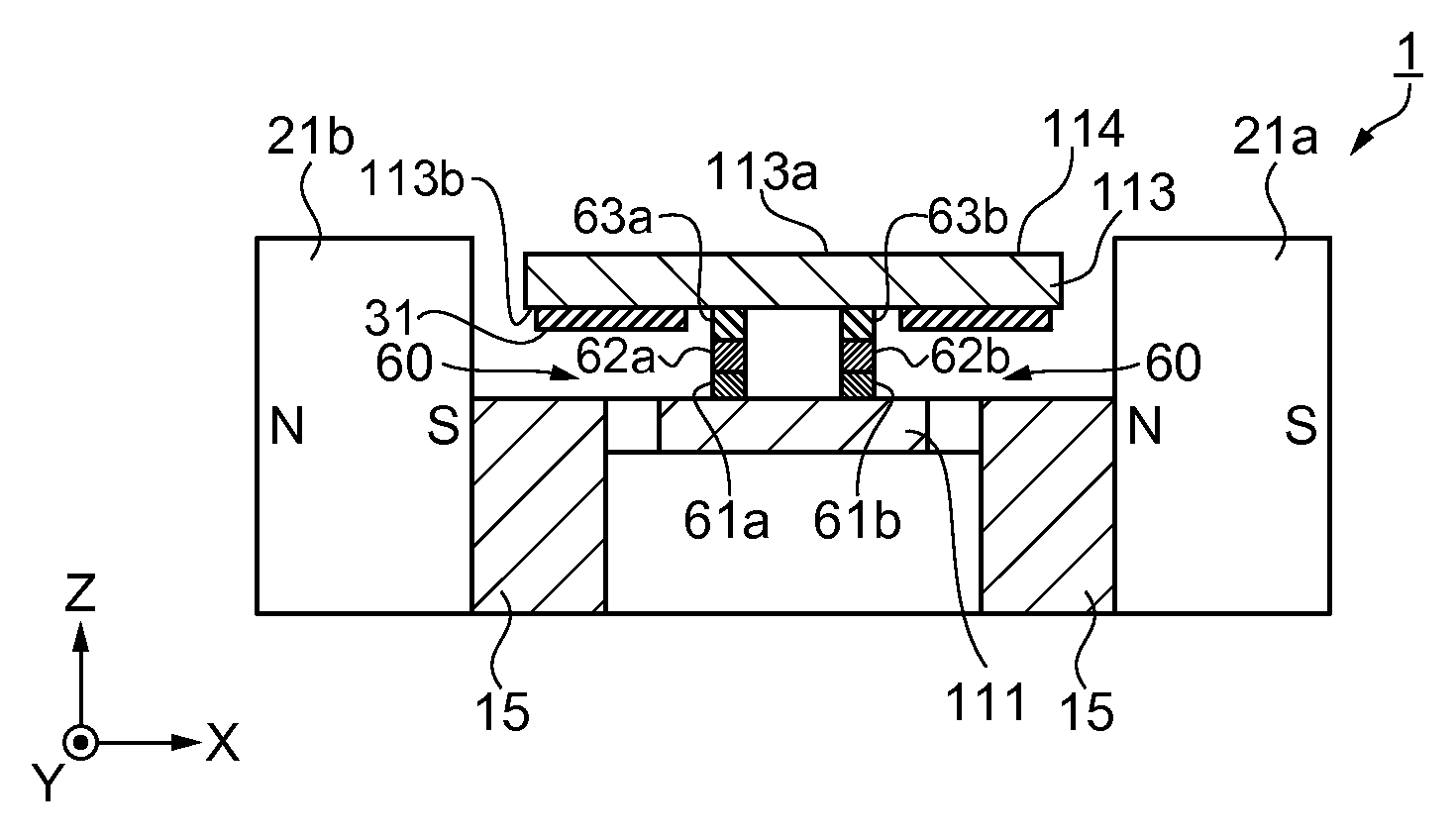
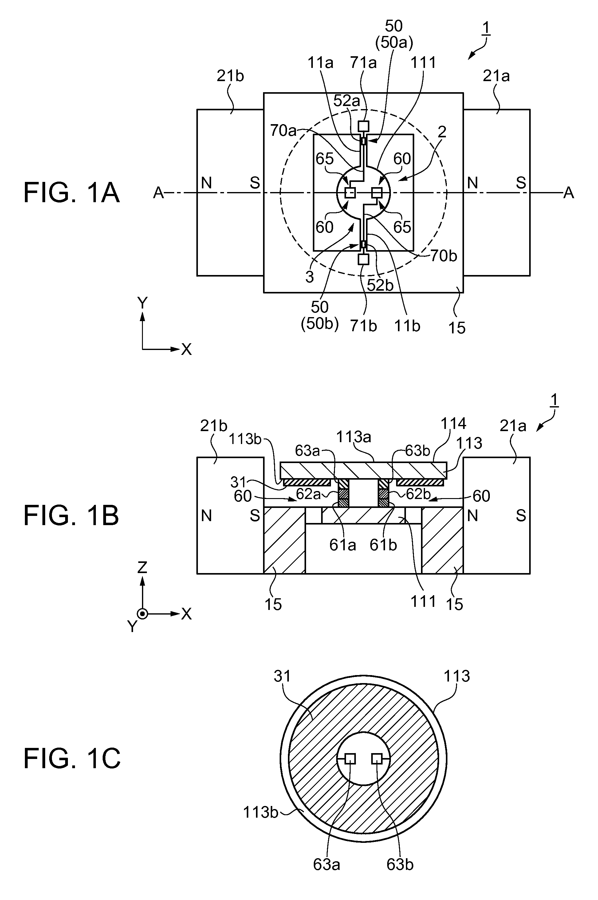
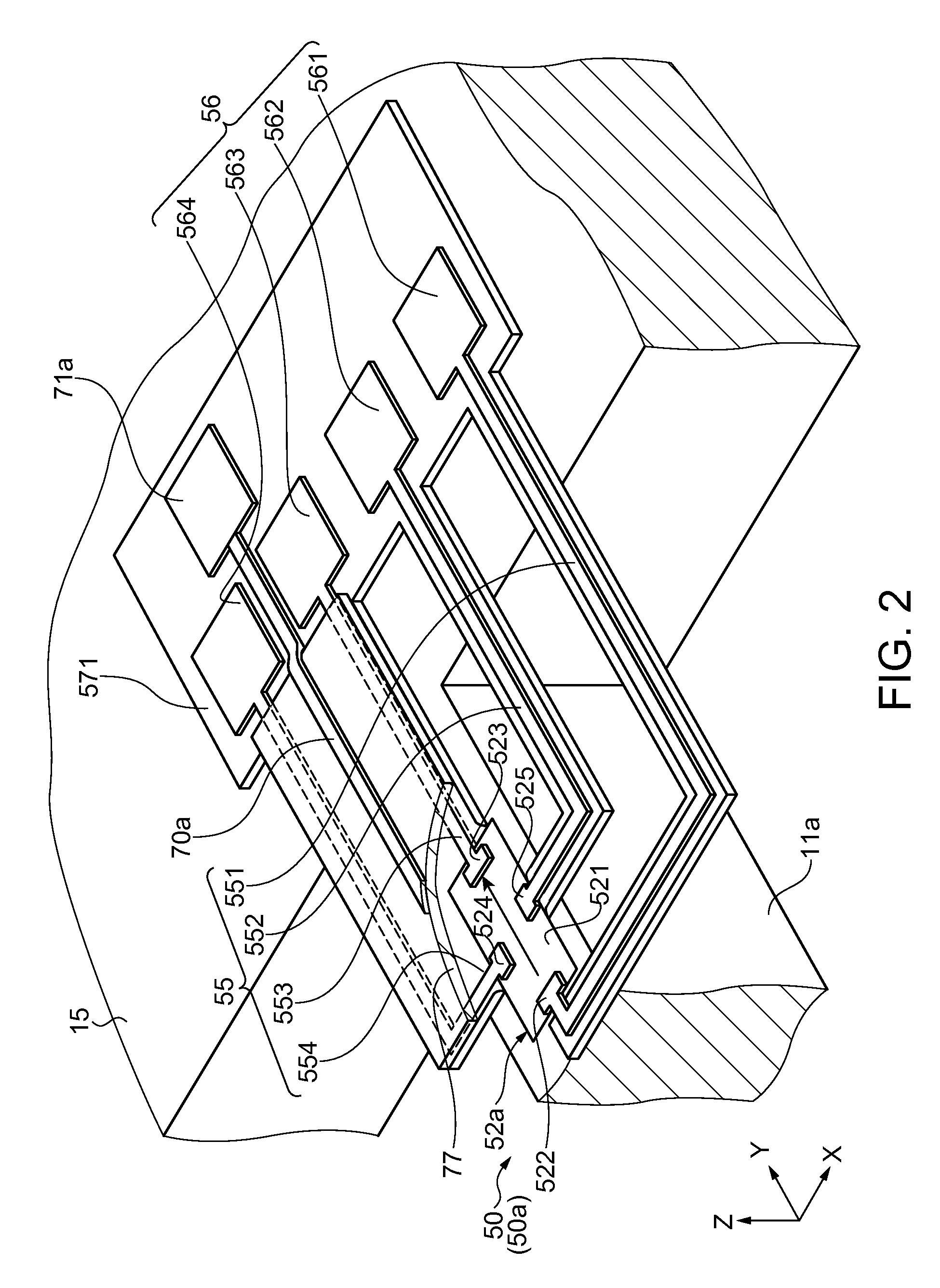
[0043]Firstly, a configuration of an actuator will be explained. It should be noted that in the present embodiment, the explanation will be presented citing a light scanner, as an actuator, as an example. FIGS. 1A through 1C show the configuration of a light scanner according to the present embodiment, wherein FIG. 1A is a plan view, FIG. 1B is a cross-sectional view along the A-A line in FIG. 1A, and FIG. 1C is a plan view of a reflecting section. Further, FIG. 2 is a partial enlarged view of the light scanner according to the present embodiment. As shown in FIGS. 1A through 1C, the light scanner 1 is provided with a movable plate 111, a first axial member 3 for swingably supporting the movable plate 111 around a first axis, a reflecting section 113 fixed to the movable plate 111 and having a reflecting surface 114 for reflecting light, and a coil 31 disposed on an opposite surface of the reflecting section 113 to the reflecting surface 114....
second embodiment
Configuration of Actuator (Light Scanner)
[0077]Then, a configuration of an actuator according to a second embodiment will be explained. It should be noted that in the present embodiment, the explanation will be presented citing a light scanner, as an actuator, as an example.FIG. 7 is a plan view showing a configuration of the light scanner according to the present embodiment, and FIG. 8 is a cross-sectional view showing the configuration of the light scanner according to the present embodiment. Further, FIG. 7 is a plan view viewed through the reflecting section, and FIG. 8 is a cross-sectional view along the A-A line in FIG. 7. It should be noted that the same components and so on as those in the first embodiment are denoted with the same reference symbols.
[0078]As shown in FIGS. 7 and 8, the light scanner 1a is provided with the movable plate 111, first axial members 12a, 12b for swingably supporting the movable plate 111 around the first axis (the Y axis), the reflecting section ...
third embodiment
Configuration of Actuator (Light Scanner)
[0114]Then, a configuration of an actuator according to a third embodiment will be explained. It should be noted that in the present embodiment, the explanation will be presented citing a light scanner, as an actuator, as an example. FIG. 11 is a plan view showing a configuration of the light scanner according to the present embodiment, and FIG. 12 is a cross-sectional view showing the configuration of the light scanner according to the present embodiment. Further, FIG. 11 is a plan view viewed through the reflecting section, and FIG. 12 is a cross-sectional view along the A-A line in FIG. 11. It should be noted that the same components and so on as those in the second embodiment are denoted with the same reference symbols. Further, portions with configurations different from those of the second embodiment will mainly be explained.
[0115]As shown in FIGS. 11 and 12, the light scanner 1b is provided with the movable plate 111, the first axial m...
PUM
 Abstract
Description
Claims
Application Information
 - R&D
- Intellectual Property
- Life Sciences
- Materials
- Tech Scout
- Unparalleled Data Quality
- Higher Quality Content
- 60% Fewer Hallucinations
Browse by: Latest US Patents, China's latest patents, Technical Efficacy Thesaurus, Application Domain, Technology Topic, Popular Technical Reports.
© 2025 PatSnap. All rights reserved.Legal|Privacy policy|Modern Slavery Act Transparency Statement|Sitemap|About US| Contact US: help@patsnap.com


