Power receptacle assembly

a technology for power receptacles and assemblies, applied in the direction of electrical equipment, connection, coupling device connections, etc., can solve the problems of cost, large space occupation, and increased cost of die opening and product inventory management of conventional power receptacles, and achieve the effect of flexibly altering the appearance of power receptacles

Inactive Publication Date: 2016-08-23
OOSTERMAN DOUGLAS J
View PDF8 Cites 6 Cited by
  • Summary
  • Abstract
  • Description
  • Claims
  • Application Information

AI Technical Summary

Benefits of technology

[0006]The present invention aims to solve existing problems with the production and application of conventional power receptacles for use with plugs of various electrical appliances or 3C products, by providing a power receptacle characterized in that: a second housing is engaged with at least a conventional receptacle unit, and at least a functional receptacle is engaged with a first housing. Thus, power receptacle manufacturers can alter the appearance of the power receptacle flexibly during a manufacturing process, thereby allowing users to make proper choices as needed.
[0007]The first objective of the present invention is to provide a power receptacle comprising a first housing, a second housing, one or more receptacle units, one or more functional receptacles, and a decorative bordered frame. Two or more through holes are disposed at the lower portions of two opposing sides of the first housing to admit a hook portion formed by extending downward two outer sides of the second housing engaged with one or more receptacle unit and admit a hook portion formed by extending downward two outer sides of one or more functional receptacle. Thus, not only does the power receptacle feature a flexible combination of a conventional receptacle unit and functional receptacle in operation to meet user needs and application needs, but the assembly process also features simple engagement and precise positioning.
[0008]The second objective of the present invention is to provide a power receptacle which comprises a first housing, a second housing, one or more receptacle units, one or more functional receptacles, and a decorative bordered frame. One or more receiving spaces are disposed on the active surface of the second housing. A recess is formed at each of two opposing peripheral flanges of each receiving space. The abutting portions formed by extending two opposing outer sides of the receptacle unit upward are guided into the receiving space of the second housing and passed through the recesses to receive a positional restriction imposed by the peripheral flanges adjacent to the bottom thereof. Hence, the receptacle units attain a modularization design, get engaged with the first housing flexibly and quickly, and can be removed from the power receptacle without destroying related components.
[0009]The third objective of the present invention is that the hook portions, which are formed by extending downward two outer sides of the second housing engaged with the receptacle unit and extending downward two outer sides of the functional receptacle engaged with the first housing, manifest appropriate elasticity.
[0010]The fourth objective of the present invention is that an upward portion of each corner in the internal space of the first housing engaged with the functional receptacle and that the second housing engaged with the receptacle unit extends to form a hook portion. The hook portions of the first housing are inserted into a space positioned beside each protruding portion extending downward from a corresponding corner as soon as the decorative bordered frame covers the upper periphery of the first housing, to enable the quick positioning required for coupling the decorative bordered frame and the first housing together and impose a peripheral positional restriction on the second housing and the functional receptacle engaged with the first housing, thereby further effectuating changes in appearance.
[0011]The fifth objective of the present invention is that two or more downward sloping guide portions are disposed on two opposing sides facing the internal space of the first housing engaged with the functional receptacle and the second housing engaged with the receptacle unit. Thus, the functional receptacle can engage with or disengage from two outer hook portions of the second housing smoothly.

Problems solved by technology

However, the aforesaid two power receptacles in operation are usually restricted to a single function.
In addition, power receptacle manufacturers are further confronted with a problem.
That is, die opening and product inventory management of the conventional power receptacles incur costs and take up much space.

Method used


Image

  • Power receptacle assembly
  • Power receptacle assembly
  • Power receptacle assembly

Examples


Embodiment Construction

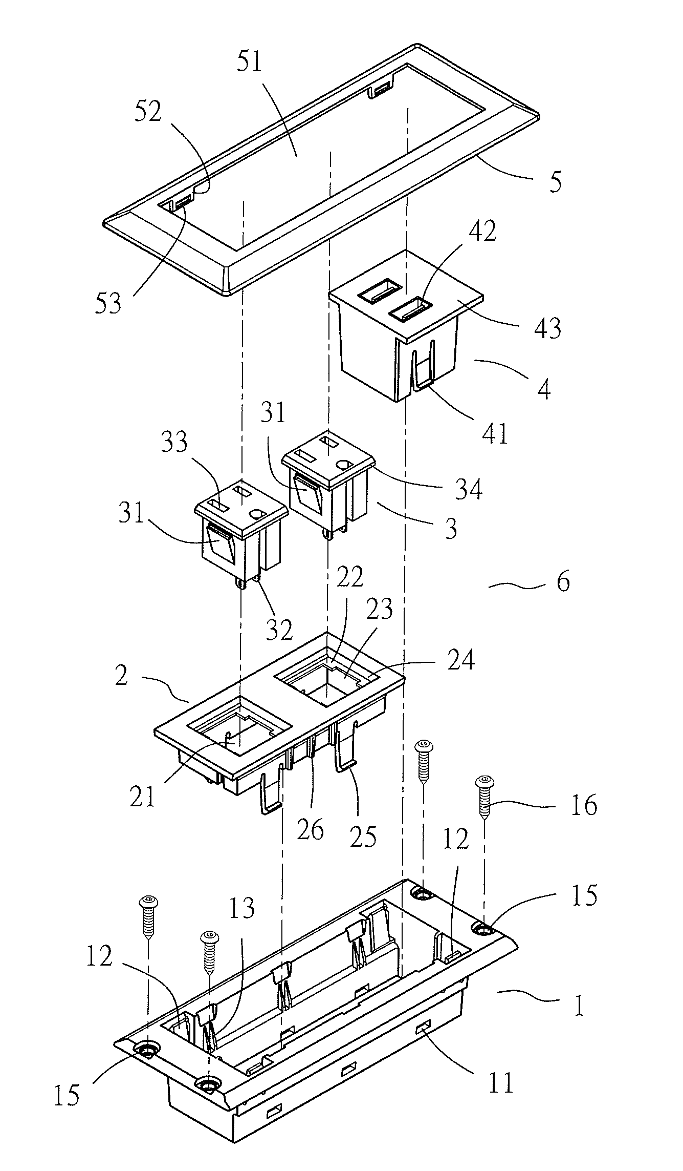
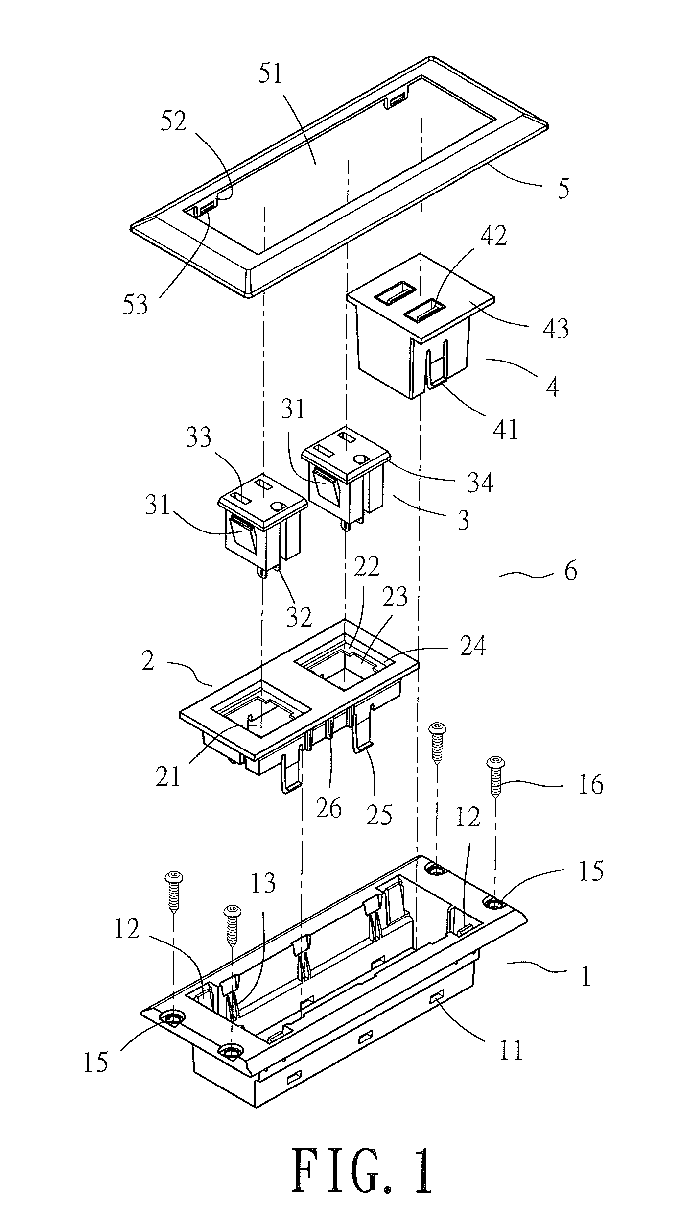
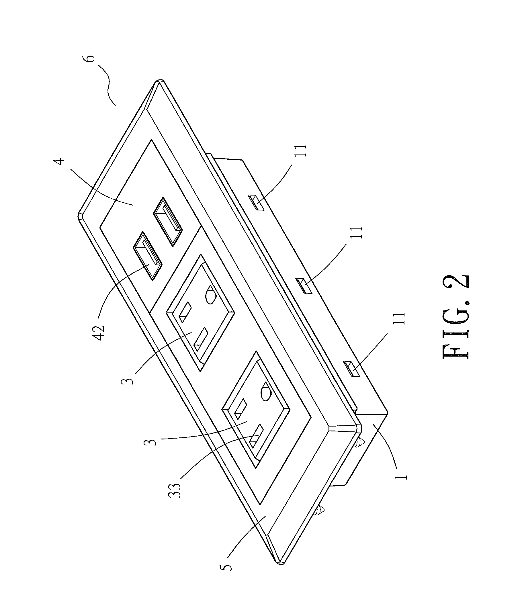
[0028]A power receptacle assembly (shown in FIG. 1) of the present invention, provided in the form of a power receptacle 6, comprises a first housing 1, a second housing 2, one or more receptacle units 3, one or more functional receptacles 4, and a decorative bordered frame 5.

[0029]The first housing 1, which is a basic component of a power receptacle, has a predetermined width and depth. Two or more through holes 11 are disposed at lower portions of two opposing sides of the first housing 1, respectively. An upward portion of each corner in the internal space of the first housing 1 extends to form a hook portion 12. Two or more downward sloping guide portions 13 are disposed on two opposing sides facing the internal space of the first housing 1, respectively. One or more power cord outlets 14 and one or more USB card outlets 17 enable a power cord 35 and a USB cord 44 to output (shown in FIG. 3 and FIG. 5) and are disposed at the bottom of the first housing 1. Holes 15 are disposed ...


PUM


Abstract

A power receptacle assembly includes a first housing, a second housing, one or more receptacle units, one or more functional receptacles, and a decorative bordered frame. Two or more through holes are disposed at lower portions of two opposing sides of the first housing to admit a hook portion formed by extending downward two outer sides of the second housing engaged with the one or more receptacle units and admit a hook portion formed by extending downward two outer sides of the one or more functional receptacle. Not only does the power receptacle feature a flexible combination of a conventional receptacle unit and a functional receptacle in operation to meet user needs and application needs, but the assembly process also features simple engagement and precise positioning.

Description

BACKGROUND OF THE INVENTION[0001]1. Technical Field[0002]The present invention relates to power receptacle assemblies and, more particularly, to a power receptacle for admitting a plug of various electrical appliances or 3C products. The power receptacle comprises a first housing engaged with at least a functional receptacle, and a second housing engaged with at least a conventional receptacle unit, such that power receptacle manufacturers can alter the appearance of the power receptacle flexibly during a manufacturing process, thereby allowing users to make proper choices as needed.[0003]2. Description of Related Art[0004]A conventional power receptacle for use with a plug at one end of a power cord of various electrical appliances or 3C products usually has a plurality of slots for admitting positive and negative pins of the plug. A control switch is disposed beside the slots and is adapted to switch between ON / OFF states to not only allow the power to be turned off without unplug...

Claims


Application Information

Patent Timeline
Patent Type & Authority Patents(United States)
IPC IPC(8): H01R13/60H01R13/506H01R27/02H02G3/10H02G3/14
CPCH01R27/02H01R13/506H02G3/10H02G3/14
Inventor OOSTERMAN, DOUGLAS J.BACON, GARY R.BROPHY, JOSEPH T.
Owner OOSTERMAN DOUGLAS J
Why Eureka
Try Eureka