Connector

a technology of connecting rods and connectors, applied in the direction of electrical equipment, incorrect coupling prevention, coupling device connection, etc., can solve the problem of high manufacturing cost, achieve excellent versatility, reduce cost, and improve the reliability of detecting the incomplete connection state of the first and second housings

Active Publication Date: 2016-08-30
SUMITOMO WIRING SYST LTD
View PDF13 Cites 4 Cited by
  • Summary
  • Abstract
  • Description
  • Claims
  • Application Information

AI Technical Summary

Benefits of technology

[0011]The detector has at least one regulating portion configured to contact the lock arm in a direction to prevent a release of a locked state to the second housing when the first and second housings are connected properly. Accordingly, the locked state of the lock arm to the second housing is not released inadvertently.
[0014]The resilient arms may be spaced from each other and may be deflected and deformed toward each other in the process of connecting the first and second housings. A resilient member may be between the resilient arms and may be configured to be pressed by the resilient arms and deformed resiliently to assist separation forces by the resilient arms. Thus, the separation forces for separating the second housing from the first housing can be increased so that reliability of detecting the incompletely connected state of the first and second housings is improved.
[0015]The resilient member may be a single torsion spring. Accordingly, versatility is excellent. Further, cost is suppressed and parts management is facilitated since it is not necessary to prepare a plurality of torsion springs. In addition, the single torsion spring between the two resilient arms applies equal separation forces to both resilient arms so that forces are applied to the second housing in a well-balanced manner.
[0017]According to the invention, when the connecting operation of the first and second housings is stopped at an intermediate stage (e.g. halfway), the separation force of the resilient arm deflected and deformed in the direction intersecting the connecting direction of the first and second housings is applied to the second housing and causes the second housing to be separated from the first housing. Thus, the first and second housings are not left in an incompletely connected state. The at least one resilient arm may be integral or unitary with the detector. Therefore, unlike the prior art, the detector need not have a spring accommodating portion for accommodating a spring. As a result, the structure of the detector is not complicated.

Problems solved by technology

The spring accommodating portions complicate the spring holder and further complicate a mold for molding the spring holder, thereby leading high manufacturing costs.

Method used


Image

  • Connector
  • Connector
  • Connector

Examples


Embodiment Construction

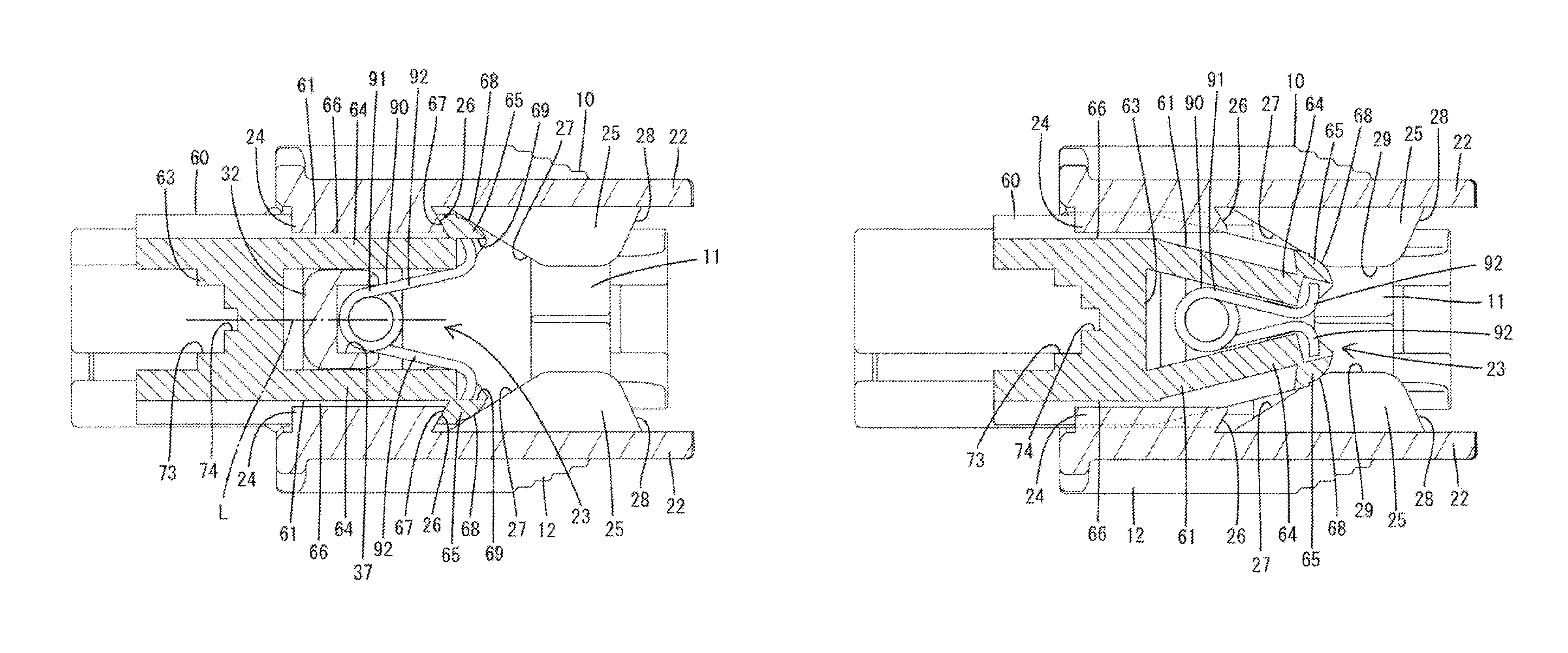
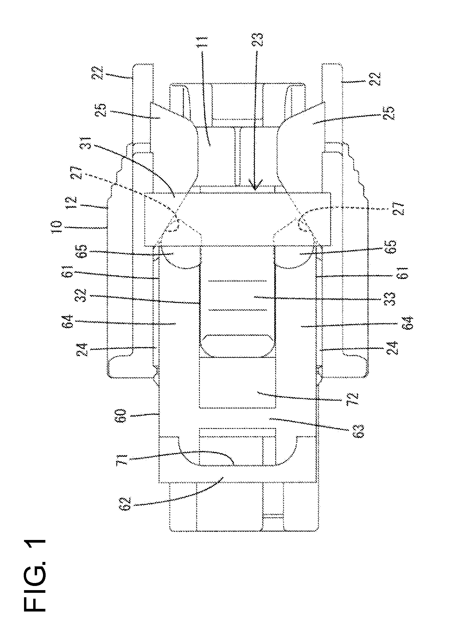
[0036]An embodiment of the invention is described with reference to the drawings. A connector in accordance with an embodiment of the invention includes a first housing 10 and a second housing 40 that are connectable to each other. A detector 60 is mounted movably on the first housing 10, and a torsion spring 90, as a resilient member, is mounted in the first housing. In the following description, ends of the first and second housings 10, 40 facing each other when a connecting operation is started are referred to as the front ends concerning a front-back direction. A vertical direction is based on FIGS. 5 to 8, 11, 12, 14, 15 and 17, and a width direction is synonymous with a lateral direction of FIGS. 11 and 14.

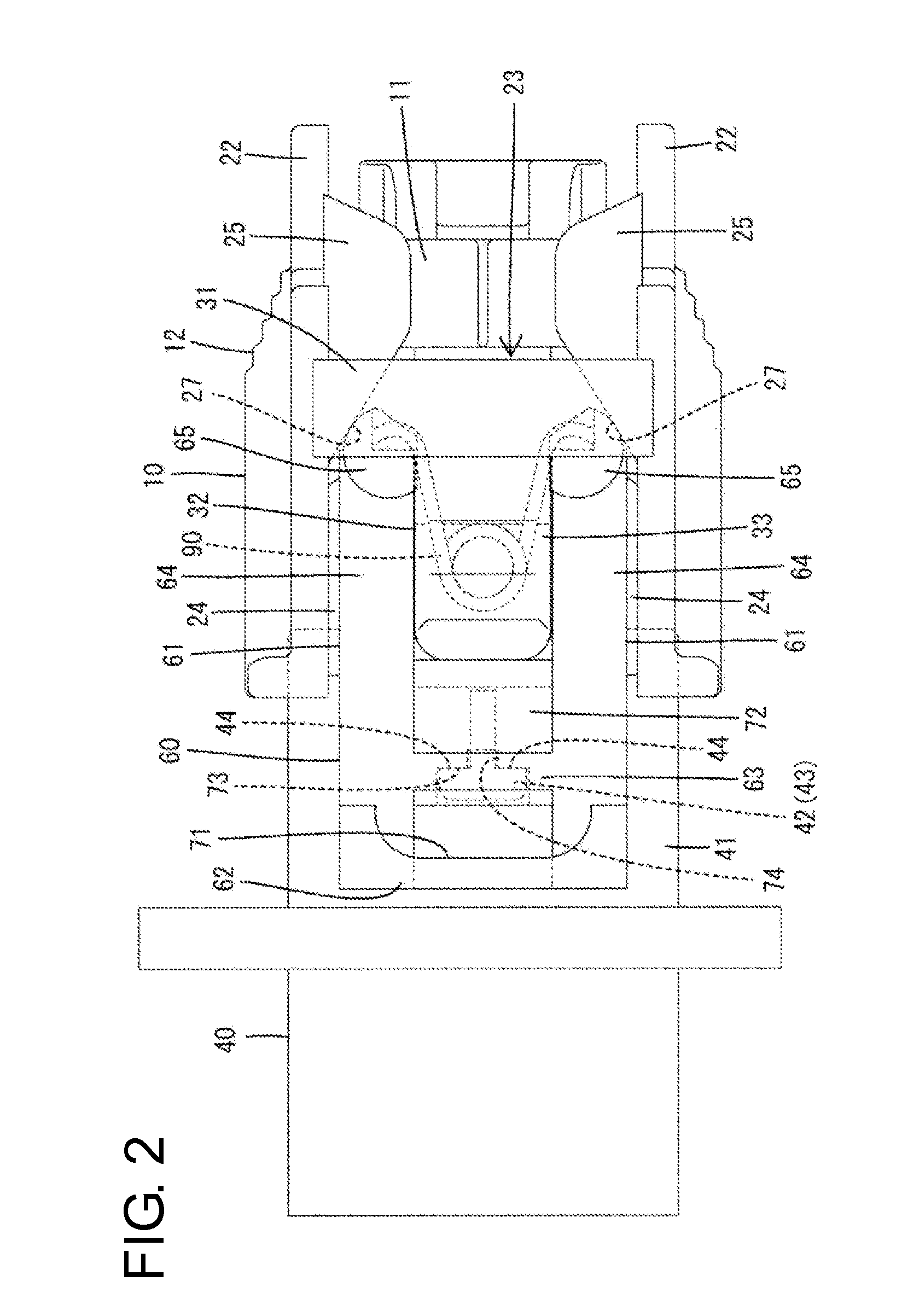
[0037]The second housing 40 is made of synthetic resin and is configured as a general-purpose male connector housing to be coupled to an unillustrated device. As shown in FIGS. 14 to 17, the second housing 40 includes a forwardly open tubular receptacle 41, and tabs 46 of ma...


PUM


Abstract

A detector (60) configured to be pressed and moved by a second housing (40) in the process of connecting first and second housings (10, 40) and separate the second housing 40 from the first housing (10) when a connecting operation of the first and second housings is stopped halfway is mounted on the first housing (10). The detector (60) integrally includes a resilient arm (61) configured to apply a separation force to the second housing (40) in a direction to separate the second housing (40) from the first housing (10) by sliding on a guiding surface (27) in one of the first and second housings (10, 40) to be deflected and deformed in a direction intersecting a connecting direction of the first and second housings (10, 40) in the process of connecting the first and second housings (10, 40).

Description

BACKGROUND[0001]1. Field of the Invention[0002]The invention relates to a connector.[0003]2. Description of the Related Art[0004]Japanese Unexamined Patent Publication No. 2000-68003 discloses a connector with a connection detecting function. This connector includes male and female housings that are connectable to each other and a spring holder movably mounted on the female housing. The spring holder has a left and right spring accommodating portions capable of accommodating coil springs as separate bodies.[0005]The coil springs accommodated in the spring accommodating portions of the spring holder contact ribs on the male housing in the process of connecting the two housings and are pressed by the ribs to compress gradually as the connection proceeds. If a connecting operation of the two housings is stopped halfway, the coil springs release biasing forces accumulated thus far to separate the male housing from the female housing. Thus, the two housings are not left in an incompletel...

Claims


Application Information

Patent Timeline
Patent Type & Authority Patents(United States)
IPC IPC(8): H01R12/82H01R13/627H01R13/66H01R13/641
CPCH01R13/6272H01R13/6273H01R13/641H01R13/6683
Inventor HORIUCHI, HIDEFUMI
Owner SUMITOMO WIRING SYST LTD
Why Eureka
Try Eureka