Method of assembling and adjusting a multi-beam scanning optical apparatus and method of manufacturing a multi-beam scanning optical apparatus

a scanning optical apparatus and multi-beam technology, applied in the direction of optical elements, visual presentation using printers, instruments, etc., can solve the problems of limiting the rotation speed, limiting the size of the polygon, and affecting the quality of the image, so as to achieve high-quality printing and suppress the effect of image degradation

Active Publication Date: 2016-09-13
CANON KK
View PDF9 Cites 71 Cited by
  • Summary
  • Abstract
  • Description
  • Claims
  • Application Information

AI Technical Summary

Benefits of technology

[0008]In view of the above, the present invention provides a method of assembling and adjusting a multi-beam scanning optical apparatus and a method of manufacturing a multi-beam scanning optical apparatus that enable a high-speed and highly-fine printing by sufficiently correcting a scanning position misalignment of a multi-beam with a uniform multi-beam interval in a sub-scanning direction.
[0010]According to the present invention, degradation of an image can be suppressed and a high-speed and highly-fine printing can be achieved in the multi-beam scanning optical apparatus.

Problems solved by technology

However, the measures (1) and (2) raise such problems as a limit of the rotation speed and a restriction of a size of the polygon mirror due to the increase of the number of the mirror planes thereof, respectively, and hence a multi-beam scanning optical apparatus using a multi-beam light source of the measure (3) is increasingly used.
However, in the multi-beam scanning optical apparatus, a scanning interval misalignment or a scanning position misalignment (misregistration) in a sub-scanning direction of the multi-beam may occur due to a mounting error of each optical element.
H11-326804 and Japanese Patent Application Laid-Open No. 2004-258182 are applied to correct the scanning position misalignment (misregistration) in the multi-beam scanning optical apparatus, there occurs a problem that the sub-scanning interval between beams of the multi-beam on the surface of the photosensitive drum becomes non-constant relative to an image height.

Method used


Image

  • Method of assembling and adjusting a multi-beam scanning optical apparatus and method of manufacturing a multi-beam scanning optical apparatus
  • Method of assembling and adjusting a multi-beam scanning optical apparatus and method of manufacturing a multi-beam scanning optical apparatus
  • Method of assembling and adjusting a multi-beam scanning optical apparatus and method of manufacturing a multi-beam scanning optical apparatus

Examples


first embodiment

[0037

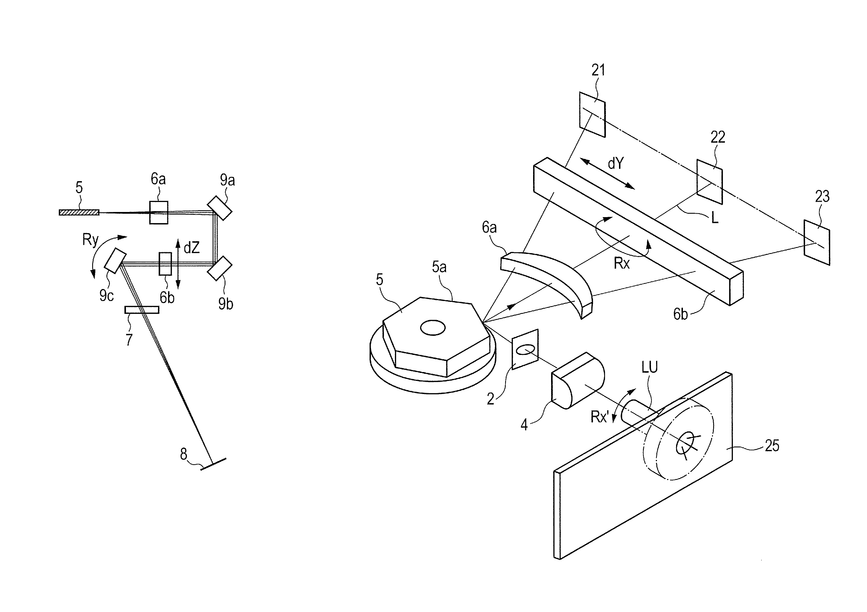
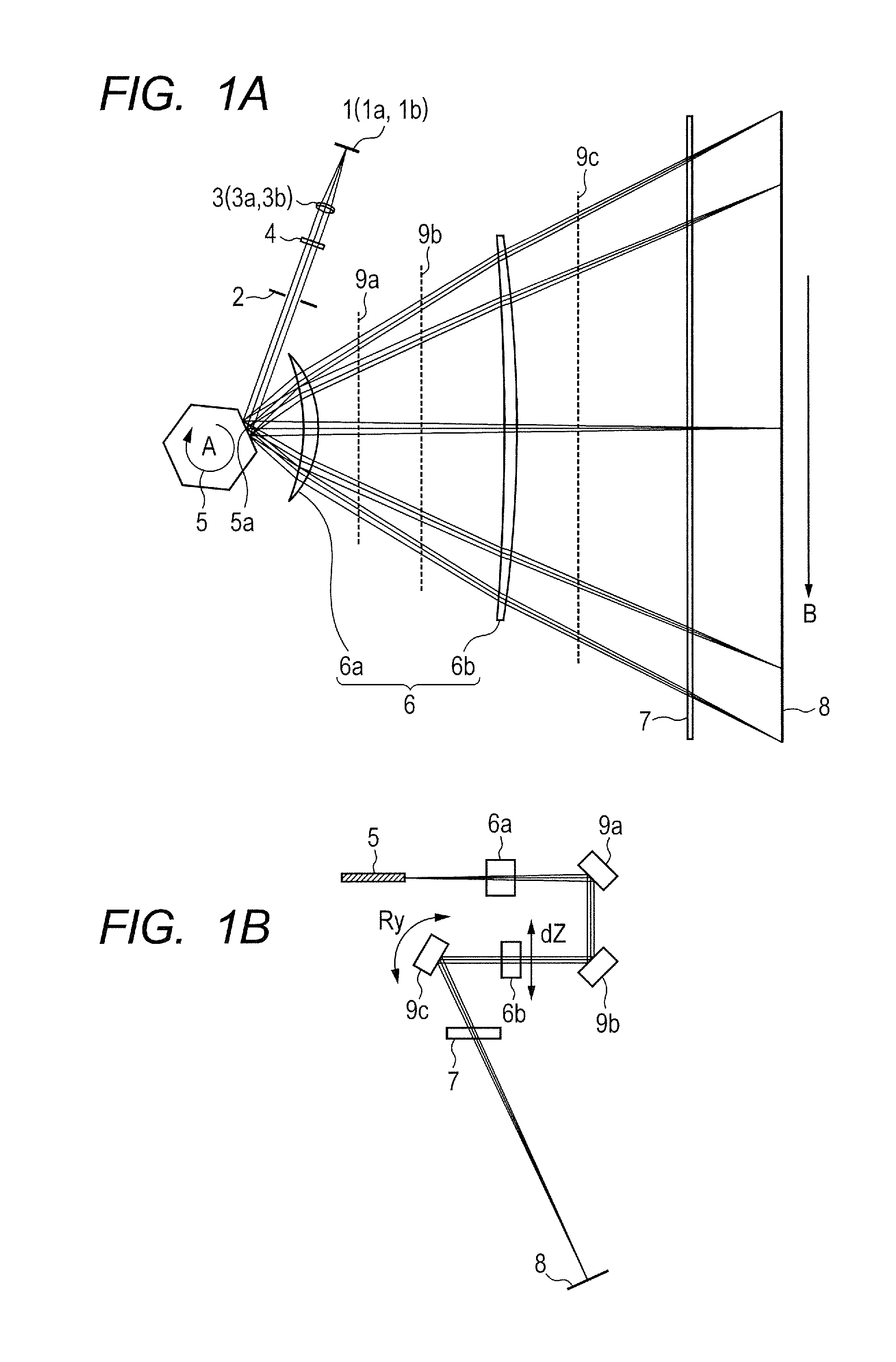
[0038]FIG. 1A is a view illustrating a main-scanning cross section of a scanning optical apparatus according to a first embodiment of the present invention. FIG. 1B is a view illustrating a sub-scanning cross section of the scanning optical apparatus according to the first embodiment of the present invention. The main scanning direction (Y direction) identifiable in this context is a direction perpendicular to a rotation axis of a deflecting unit 5 and an optical axis of an imaging optical system 6 (X direction) (a direction along which a light beam is deflected by the deflecting unit 5 (deflection scanning)). The sub-scanning direction (Z direction) identifiable in this context is a direction parallel to the rotation axis of the deflecting unit 5. The main-scanning cross section identifiable in this context is a plane including the optical axis of the imaging optical system 6 and the main scanning direction. The sub-scanning cross section identifiable in this context is a cros...

second embodiment

[0066

[0067]FIG. 12 is a diagram illustrating a sensor arrangement in a method of assembling and adjusting a multi-beam scanning optical apparatus according to a second embodiment of the present invention, in which elements assigned with the same reference symbols are the same as those described in the first embodiment. FIG. 13 is a flowchart of an assembling and adjusting process according to the second embodiment. The second embodiment is different from the first embodiment in that an optical sensor (e.g., a line CCD) 40 (second optical sensor) is arranged right in front of a toric lens 6b (on the deflecting unit side). Instead of evaluating the asymmetry by detecting an interval of the irradiated positions in the sub-scanning direction with optical sensors 21 and 23, a position of the light beam in the sub-scanning direction, which is entered into the toric lens 6b is detected with the optical sensor 40. If a detected incident position ΔZ in the sub-scanning direction is deviated ...


PUM

PropertyMeasurementUnit
heightsaaaaaaaaaa
heightsaaaaaaaaaa
heightaaaaaaaaaa

Abstract

Provided is a method of assembling and adjusting multi-beam scanning optical apparatus including a light source unit having multiple light emitting points, a deflecting unit configured to deflect multiple light beams emitted from the light source unit, and an imaging optical system configured to image the multiple light beams deflected by the deflecting unit on a surface to be scanned, the method including: adjusting incident positions of the multiple light beams in a sub-scanning direction, which are entered into an imaging optical element constituting the imaging optical system to adjust irradiated positions of the multiple light beams on the surface to be scanned; and adjusting the irradiated positions of the multiple light beams on the surface to be scanned in the sub-scanning direction without changing the incident positions.

Description

BACKGROUND OF THE INVENTION[0001]1. Field of the Invention[0002]The present invention relates to a method of assembling and adjusting a multi-beam scanning optical apparatus and a method of manufacturing a multi-beam scanning optical apparatus, and more particularly, to a method of assembling and adjusting a multi-beam scanning optical apparatus and a method of manufacturing a multi-beam scanning optical apparatus, which are suitable for a multi-beam scanning optical apparatus used for an image forming apparatus employing an electrophotographic process, such as a laser beam printer, a digital copy machine, and a multi-function printer.[0003]2. Description of the Related Art[0004]In a scanning optical apparatus of an image forming apparatus such as a laser beam printer (LBP), conventionally, a light beam emitted from a light source unit, which is optically modulated in accordance with an image signal, is periodically deflected by a deflecting unit including a rotating polygon mirror....

Claims


Application Information

Patent Timeline
Patent Type & Authority Patents(United States)
IPC IPC(8): H01S4/00G02B26/12B41J2/47G06K15/12G02B26/08
CPCG02B26/126B41J2/473G02B26/0825G02B26/127G06K15/1219G06K15/1257G02B26/123Y10T29/49002
Inventor TANIMURA, KEN
Owner CANON KK
Why Eureka
Try Eureka