

Automatic transmission equipped with friction element having locking mechanism attached thereto, and control method therefor
a technology of friction element and automatic transmission, which is applied in the direction of fluid actuated clutches, gearing elements, non-mechanical actuated clutches, etc., can solve the problems of inability to rotate the input and output shaft of the transmission, affecting the fuel economy of the vehicle equipped with an automatic transmission, and interlocking
- Summary
- Abstract
- Description
- Claims
- Application Information
AI Technical Summary
Benefits of technology
Problems solved by technology
Method used
Image

Examples
Embodiment Construction
[0015]The following describes an embodiment of the present invention with reference to the attached drawings.
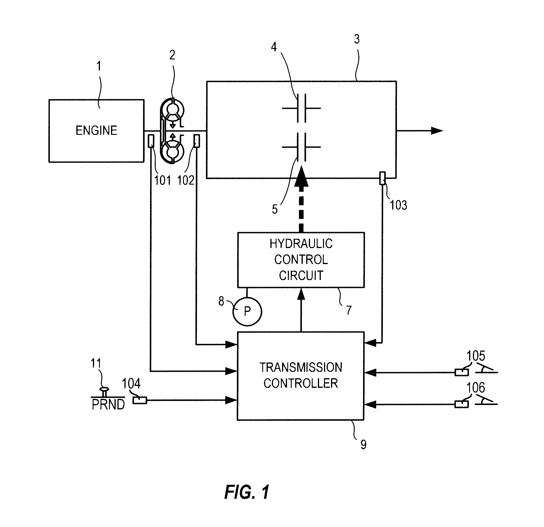
[0016]FIG. 1 shows a schematic configuration of a vehicle equipped with an automatic transmission according to the embodiment of the present invention. The vehicle includes an engine 1, a torque converter 2, and a transmission 3. An output rotation of the engine 1 is transmitted to unillustrated drive wheels via the torque converter 2, the transmission 3, and an unillustrated differential gear unit.
[0017]The transmission 3 is a step or continuously variable automatic transmission. The transmission 3 includes a reverse brake 4 and a forward clutch 5. In a state where the reverse brake 4 is engaged, the transmission 3 outputs the rotation of the engine 1 in reverse. In a state where the forward clutch 5 is engaged, the transmission 3 outputs the rotation of the engine 1 while maintaining its rotational direction.
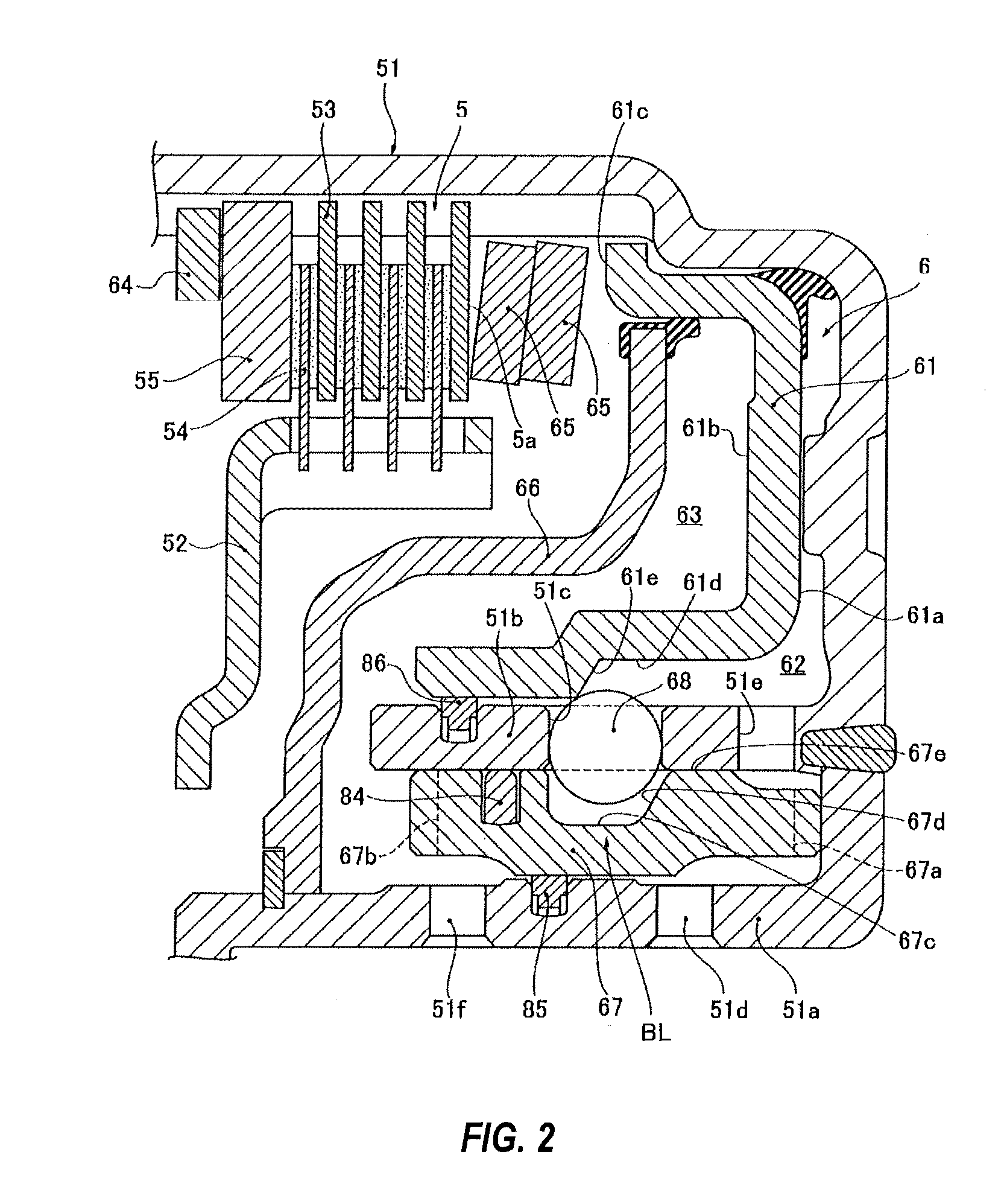
[0018]The reverse brake 4 is a traditional friction element which ...
PUM
 Abstract
Description
Claims
Application Information