
Stable hydraulic lifting dam with locking mechanism

A technology of hydraulic lifting dam and locking mechanism, applied in the field of lifting dam, can solve the problems of hydraulic equipment load and easy water leakage, and achieve the effects of strong firmness, high blocking efficiency and simple operation

Inactive Publication Date: 2021-02-05
ANHUI HUAJING MACHINERY
View PDF6 Cites 2 Cited by
  • Summary
  • Abstract
  • Description
  • Claims
  • Application Information

AI Technical Summary

Problems solved by technology

[0003] However, when the existing hydraulic lifting dam is adjusted, the discharge of the gate is easy to adjust, and the hydraulic pressure load it bears is small, but when the gate rises to intercept, the hydraulic pressure load it suffers is relatively large. It will cause load on the gate and hydraulic equipment, and the hydraulic lifting dam is mostly connected independently. When the river or water area is large, if multiple hydraulic lifting dams cannot be locked and connected, it is easy to make the hydraulic lifting dam bear in some areas. The water pressure load is not the same, which is prone to water leakage

Method used


Image

  • Stable hydraulic lifting dam with locking mechanism
  • Stable hydraulic lifting dam with locking mechanism
  • Stable hydraulic lifting dam with locking mechanism

Examples


Embodiment Construction

[0021]The technical solutions in the embodiments of the present invention will be clearly and completely described below in conjunction with the accompanying drawings in the embodiments of the present invention. Obviously, the described embodiments are only a part of the embodiments of the present invention, rather than all the embodiments. Based on the embodiments of the present invention, all other embodiments obtained by those of ordinary skill in the art without creative work shall fall within the protection scope of the present invention.

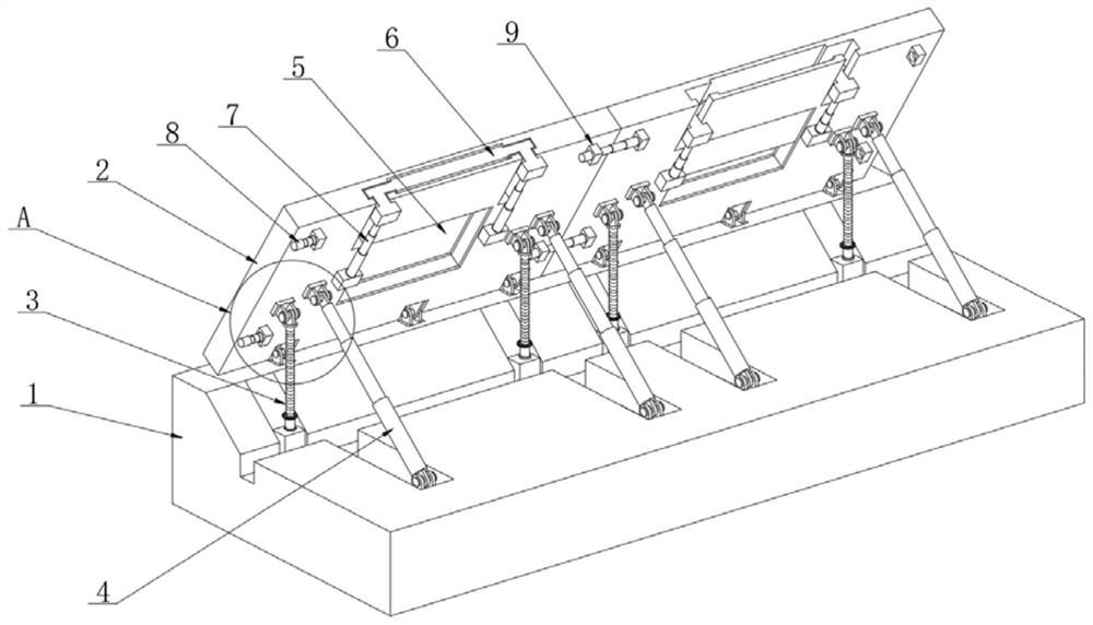
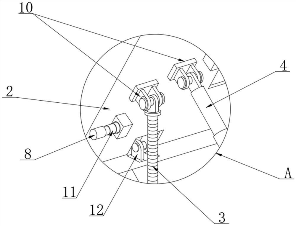
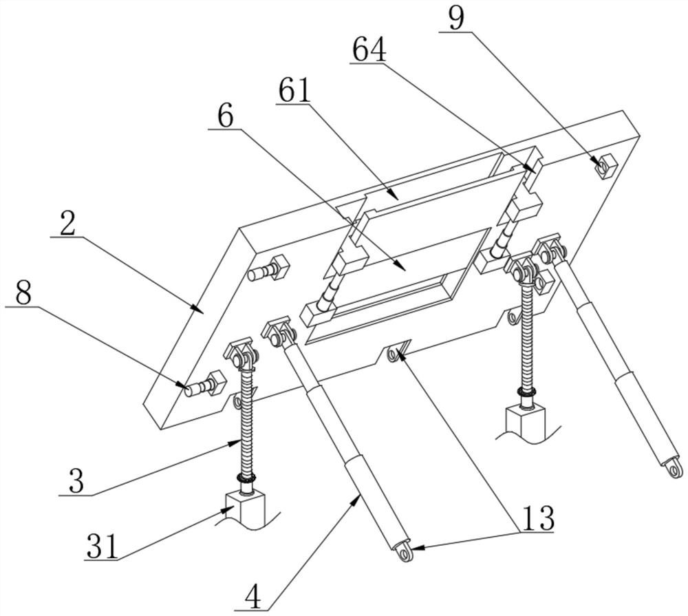
[0022]SeeFigure 1~5In the embodiment of the present invention, a stable hydraulic lifting dam with a locking mechanism includes a base 1. The base 1 is mostly made of concrete pouring, and the upper surface of the base 1 is provided with multiple gates 2 in parallel , The middle of the gate 2 is provided with a pressure relief port 5, and the middle of the gate 2 is located inside the pressure relief port 5, and a blocking plate 6 is installed....


PUM


Abstract

The invention relates to the technical field of lifting dams, and discloses a stable hydraulic lifting dam with a locking mechanism. The lifting dam comprises a base; a plurality of gates are arrangedon the upper surface of the base in parallel; a pressure relief opening is formed in the middle of each gate; a blocking plate is mounted in the middle of each gate and located on the inner side of the corresponding pressure relief opening; two main hydraulic rods are correspondingly installed on the rear surface of each gate and located on two sides of the corresponding pressure relief opening;two second lock rods are correspondingly arranged on one side edge of the rear surface of each gate and lock seats are installed on the other side edge of the rear surface of the corresponding gate and correspond to the second lock rods; and two first lock rods are installed on the side, close to the corresponding main hydraulic rods, of the rear surface of each gate. The stability of the gates isimproved, the pressure load and the tension load borne by the gates can also be improved, the second lock rods and the lock seats are used in cooperation, the blocking efficiency of the gates is high, the plurality of independent gates can be connected in series into a whole, the gates can also be rapidly formed into individual wholes, operation is easy and convenient, and implementation is convenient.

Description

Technical field[0001]The invention relates to the technical field of lifting dams, in particular to a stable hydraulic lifting dam with a locking mechanism.Background technique[0002]Hydraulic lifting dam refers to hydraulic concrete lifting dam. It is an important device used in water conservancy projects. It is widely used in agricultural irrigation, fisheries, ship locks, sea water tide, urban river landscape engineering and hydropower stations, especially military applications. Lifting dams are extremely important in military rescue and emergency rescue, as well as in flood protection and seawater tide blocking applications.[0003]However, when the existing hydraulic lifting dam is adjusted, the gate discharge and fall are easy to adjust, and the hydraulic load it bears is relatively small. However, when the gate rises and intercepts, the hydraulic load it bears is relatively large. It will load the gates and hydraulic equipment. At the same time, the hydraulic lifting dams are mo...

Claims


Application Information

Patent Timeline
IPC IPC(8): E02B7/20E02B7/40
CPCE02B7/20E02B7/40
Inventor 姚双进吴国蕾王园
Owner ANHUI HUAJING MACHINERY
Learn More