Industrial vehicle

a technology for industrial vehicles and hydraulic pumps, applied in the direction of hydraulic couplings, couplings, mechanical devices, etc., can solve the problems of insufficient torque of engines, inability to drive hydraulic pumps, and stop rotation of engines, so as to reduce the load of hydraulic pumps

Active Publication Date: 2016-05-10
NIPPON YUSOKI
View PDF16 Cites 2 Cited by
  • Summary
  • Abstract
  • Description
  • Claims
  • Application Information

AI Technical Summary

Benefits of technology

[0026]According to the industrial vehicle related to the above aspect of the invention, if the rotation speed of the engine becomes less than or equal to a predetermined value, and thus the output of the engine is lowered, an appropriate amount of hydraulic oil adjusted by the valve is discharged to the tank. In this way, the load of the hydraulic pump is reduced, whereby occurrence of an engine stall due to a shortage of the torque of the engine can be prevented before it happens.
[0027]Further, since it is sufficient if an operation of the switching valve is controlled based on only the rotation speed of the engine, compared with a case of controlling an operation of a switching valve on the basis of both the rotation speed of an engine or the pressure of the hydraulic oil, occurrence of an engine stall can be prevented by a configuration that is simple in terms of both a hardware configuration and a control system.

Problems solved by technology

In a case of using such an engine, if the load of a hydraulic pump increases, the torque of the engine is insufficient.
Thus, a hydraulic pump cannot be driven, and a phenomenon in which rotation of the engine stops (a so-called engine stall) occurs.

Method used


Image

  • Industrial vehicle
  • Industrial vehicle
  • Industrial vehicle

Examples


first embodiment

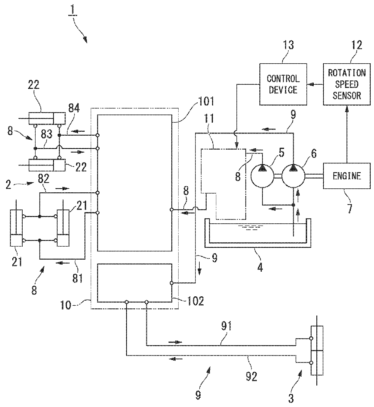
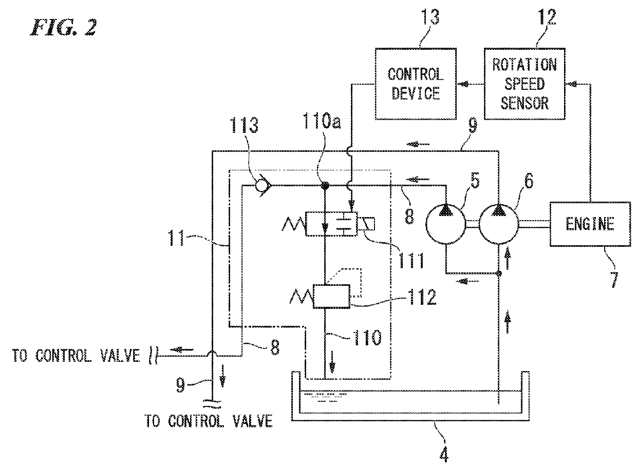
[0044]The pump load reduction system 11 is for adjusting a load which is applied to the pump for cargo handling 5, depending on the output of the engine 7. Here, FIG. 2 is a schematic diagram showing the detailed configuration of the pump load reduction system 11 regarding the forklift 1 according to the The pump load reduction system 11 has discharge piping 110, a switching valve 111, a sub-relief valve 112, and a check valve 113. The discharge piping 110 branches from the hydraulic piping for cargo handling 8 and is connected to the tank 4. The switching valve 111 is provided in the discharge piping 110. The sub-relief valve 112 is provided further to the downstream side than the switching valve 111 in the discharge piping 110. The check valve 113 is provided further to the downstream side than a branching position 110a of the discharge piping 110 in the hydraulic piping for cargo handling 8.

[0045]In addition, in this embodiment, the installation position of the sub-relief valve ...

second embodiment

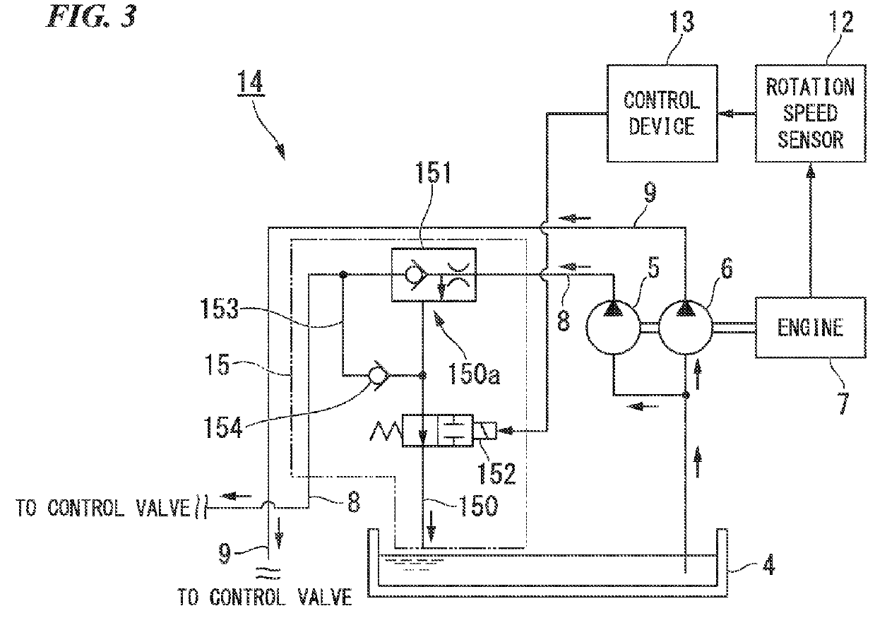
[0062]Next, the operation and effects of the forklift 14 will be described. First, in a case where the flow rate of the hydraulic oil discharged from the pump for cargo handling 5 shown in FIG. 3 is smaller than a preset flow rate, the priority valve 151 makes all the flow rate flow to the hydraulic piping for cargo handling 8 on the downstream side. In this way, when the flow rate of the hydraulic oil is small and the load of the pump for cargo handling 5 is low, regardless of a level of the output of the engine 7, all of the hydraulic oil discharged from the pump for cargo handling 5 is supplied to the hydraulically-operated device for cargo handling 2 through the control valve 10 and all the pressure of the hydraulic oil is used to operate the hydraulically-operated device for cargo handling 2.

[0063]On the other hand, in a case where the flow rate of the hydraulic oil which is discharged from the pump for cargo handling 5 shown in FIG. 3 is greater than a preset flow rate, the p...

third embodiment

[0075]Next, the operation and effects of the forklift 16 will be described. First, in a case where the rotation speed of the engine 7 which is detected by the rotation speed sensor 12 shown in FIG. 4 is larger than a predetermined value, that is, in a case where the output of the engine 7 is high, the switching valve 171 subjected to control by the control section closes the discharge piping 170. Therefore, all of the hydraulic oil discharged from the pump for cargo handling 5 is supplied to the hydraulically-operated device for cargo handling 2 through the control valve 10. In this way, when the output of the engine 7 is high and an engine stall does not easily occur, all the pressure of the hydraulic oil which is discharged from the pump for cargo handling 5 is used to operate the hydraulically-operated device for cargo handling 2.

[0076]On the other hand, in a case where the rotation speed of the engine 7 is smaller than a predetermined value, that is, in a case where the output ...


PUM


Abstract

A forklift (1) according to the present invention includes: an engine (7); a hydraulically-operated device for cargo handling (2); a pump for cargo handling (5) that is driven by the engine (7); hydraulic piping for cargo handling (8) that connects the pump for cargo handling (5) and the hydraulically-operated device for cargo handling (2); discharge piping (110) that branches from the hydraulic piping for cargo handling (8) and is connected to a tank (4); a switching valve (111) capable of switching the opening and closing of the discharge piping (110); a control device (13) that closes the discharge piping (110) when the rotation speed of the engine (7) is larger than a predetermined value, and opens the discharge piping (110) when the rotation speed of the engine (7) is less than or equal to a predetermined value; and a sub-relief valve (112) that adjusts the flow rate of hydraulic oil that is discharged from the discharge piping (110) to the tank (4), on the bases of the pressure or the flow rate of the hydraulic oil.

Description

TECHNICAL FIELD[0001]The present invention relates to an industrial vehicle in which hydraulic oil is supplied from a hydraulic pump that is driven by an engine to a hydraulically-operated device for a cargo handling operation or for steering assistance.[0002]Priority is claimed on Japanese Patent Application No. 2010-205629 filed on Sep. 14, 2010, the content of which is incorporated herein by reference.BACKGROUND ART[0003]At the time of cargo handling work such as lifting and moving heavy goods, an industrial vehicle such as a forklift is used. As the industrial vehicle, an industrial vehicle in which an arm for a cargo handling operation or power steering for steering assistance is operated by oil pressure is widely used. This industrial vehicle is provided with a hydraulic pump that is driven by an engine, and configured such that hydraulic oil discharged from the hydraulic pump is supplied to a hydraulically-operated device that is operated by oil pressure.[0004]However, in rec...

Claims


Application Information

Patent Timeline
Patent Type & Authority Patents(United States)
IPC IPC(8): F16D31/02F15B13/00B66F9/22
CPCF15B13/00B66F9/22F15B2211/50518F15B2211/50536
Inventor TSURUTA, MEGUMUITO, KEIJINAKADA, TAKUYA
Owner NIPPON YUSOKI
Why Eureka
Try Eureka