Dust collector having a hose clamp

a technology of hose clamp and dust collector, which is applied in the direction of cleaning equipment, household applications, suction cleaners, etc., can solve the problems of not being able to use snap joints to accommodate different hoses, and the hose cannot be accommodated and released quickly, so as to achieve the effect of tightening the hose, and facilitating the release of hoses

Active Publication Date: 2016-10-18
SUZHOU CLEVA ELECTRIC APPLIANCE CO LTD
View PDF8 Cites 12 Cited by
  • Summary
  • Abstract
  • Description
  • Claims
  • Application Information

AI Technical Summary

Benefits of technology

[0014]The rotatable first baffle or second baffle can be opened according to size of the hose to be accommodated; if size of the hose is big, the angle of opening is big, and the angle of opening is small when size of the hose is small. The second baffle is S-shaped, so it can open automatically when the user put the hose into the hose clamp. Due to action of the torsional spring, the first and second baffles can always clamp the hose tightly. When the operator takes the hose down, the second baffle can be opened automatically to a certain angle along with the operator's action, so the hose can be taken out favorably. In addition, the baffle is also provided with hook portion and skid-proof ribs, so the grooves on the hose can be locked with the skid-proof ribs along the C-shaped cavity, thus the hose is clamped more tightly.
[0015]Therefore, compared with the prior art, the present invention can accommodate and release the hose more quickly, and it can be used for hoses of different diameters as well.

Problems solved by technology

The hose is enwound on the dust collection power head through the snap joint, so it is troublesome to unwind the hose for use next time, and the hose cannot be accommodated and released quickly.
The dust collector is generally equipped with snap joint to accommodate hose; however, the existing snap joint is matched with a hose in pair, namely, one type of the hose can only be accommodated on one snap joint accordingly.
There is uniqueness between the hose and the snap joint, so the snap joint cannot be used to accommodate different hoses.

Method used


Image

  • Dust collector having a hose clamp
  • Dust collector having a hose clamp
  • Dust collector having a hose clamp

Examples


Embodiment Construction

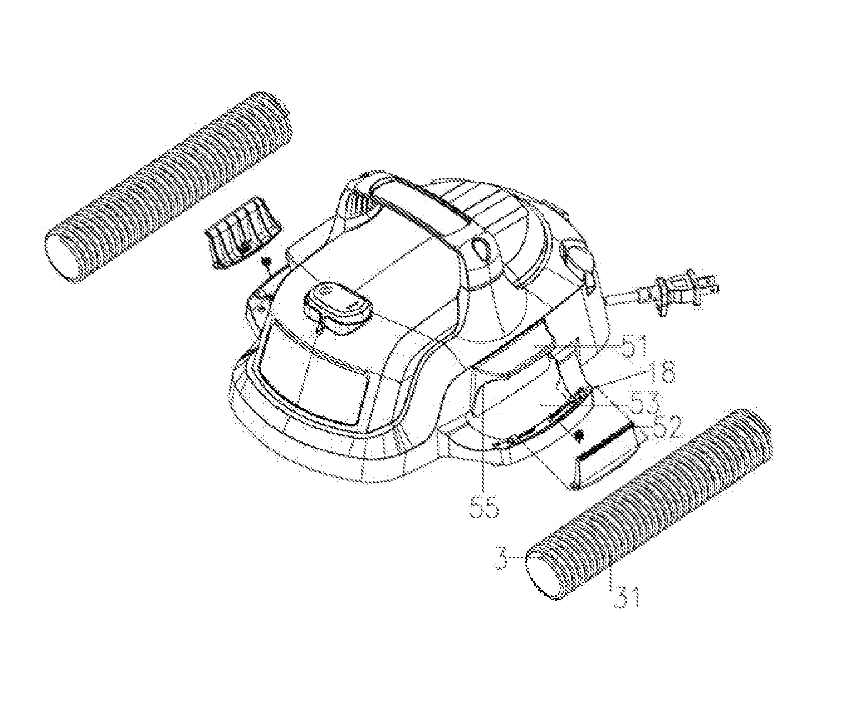
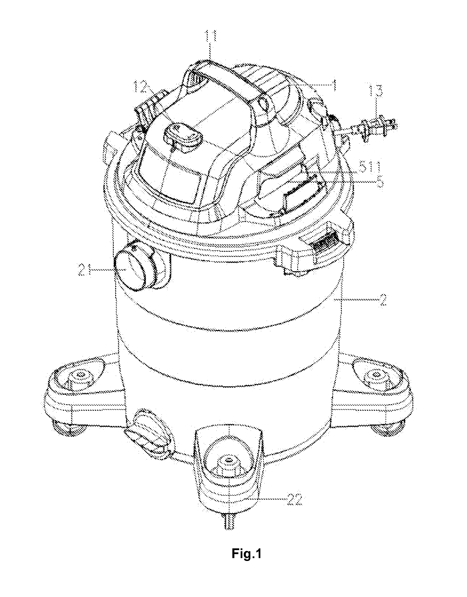
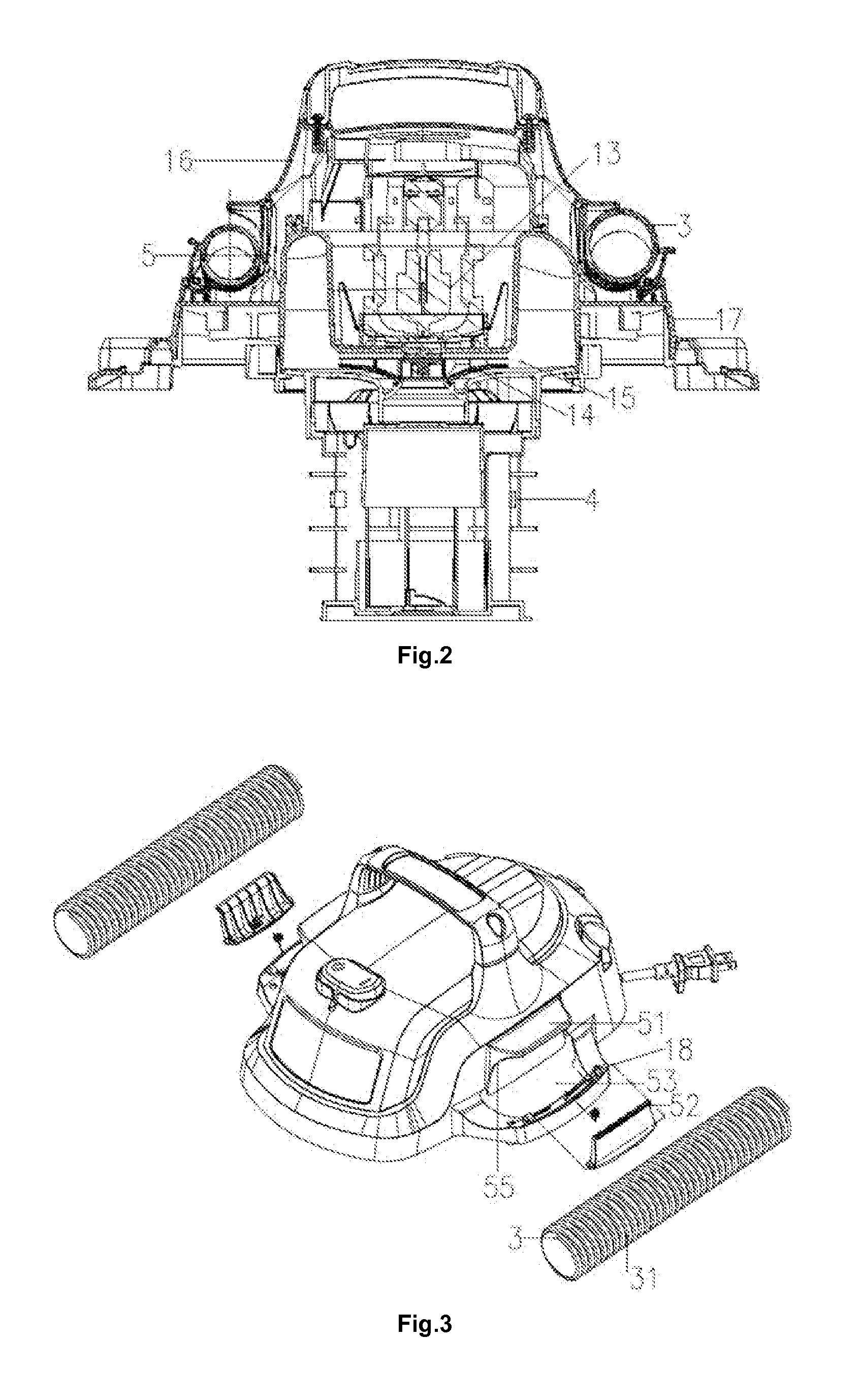
[0022]The dust collector as shown in FIG. 1 comprises a dust collection power head 1, a dust bucket 3, a hose 3 (as shown in FIG. 3) and a filtering device 4; wherein the dust collection power head is arranged on the dust bucket 2, and the dust bucket 2 is provided with an air inlet 21, through which the working airflow enters the dust bucket of the dust collector. one end of the hose can be in communication with the dust bucket; and the dust collector further comprises a hose clamp which is comprised of a first baffle, a second baffle and an elastic resetting member; at least one of the first baffle and the second baffle is a rotatable baffle, and a resetting force generated by the elastic resetting member acts on the rotatable baffle. Universal wheels 22 are provided on bottom of the dust bucket, and a handle 11 is arranged on the dust collection power head 1. A switch 12 is arranged in front of the handle, and two hose clamps 5 are arranged at two sides of the handle. The hose cl...


PUM


Abstract

A dust collector having a hose clamp, comprising a dust collection power head, a dust bucket and a hose; wherein the dust collection power head is arranged on the dust bucket, one end of the hose is in communication with the dust bucket; and the dust collector further comprises a hose clamp which is comprised of a first baffle, a second baffle and an elastic resetting member; at least one of the first baffle and the second baffle is a rotatable baffle, and a resetting force generated by the elastic resetting member acts on the rotatable baffle. Due to action of a torsional spring, the first and second baffles can always clamp the hose tightly while accommodating the hose. When the operator takes the hose down, the second baffle can be opened automatically to a certain angle along with the operator's action, so the hose can be taken out.

Description

CROSS REFERENCE TO RELATED APPLICATION[0001]This application claims priority to and incorporates by reference CN 201310216979.1 filed Jun. 4, 2013.TECHNICAL FIELD[0002]The present invention relates to a dust collector having a hose clamp.BACKGROUND ART[0003]It is necessary to accommodate the hose after using dust collector and unwind it for use next time. The hose is enwound on the dust collection power head through the snap joint, so it is troublesome to unwind the hose for use next time, and the hose cannot be accommodated and released quickly. At present, diameters of the common hoses on the market include 40 mm, 50 mm, 76 mm, 100 mm, 200 mm and so on. Different types of hoses are required for the dust collector in different environment. The dust collector is generally equipped with snap joint to accommodate hose; however, the existing snap joint is matched with a hose in pair, namely, one type of the hose can only be accommodated on one snap joint accordingly. There is uniquenes...

Claims


Application Information

Patent Timeline
Patent Type & Authority Patents(United States)
IPC IPC(8): A47L9/00A47L5/36
CPCA47L9/0036A47L5/365
Inventor ZHU, YANLING
Owner SUZHOU CLEVA ELECTRIC APPLIANCE CO LTD
Why Eureka
Try Eureka