Four-bar-linkage brake-included knee joint

Inactive Publication Date: 2012-09-18
KEN DALL ENTERPRISE
View PDF4 Cites 9 Cited by
  • Summary
  • Abstract
  • Description
  • Claims
  • Application Information

AI Technical Summary

Benefits of technology

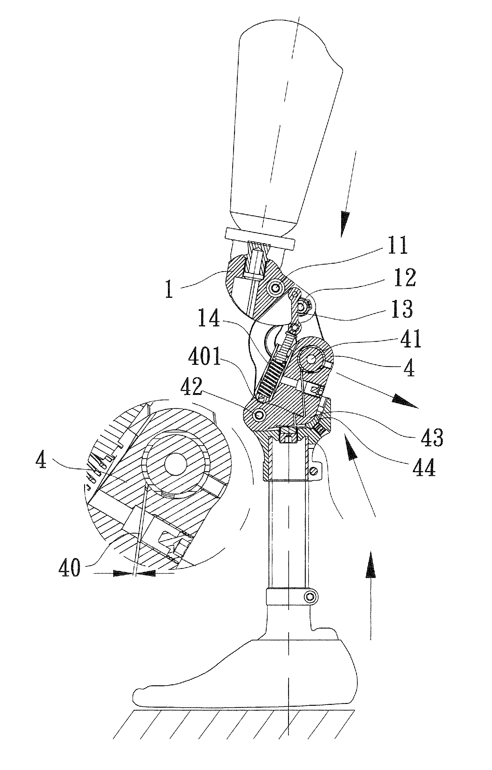
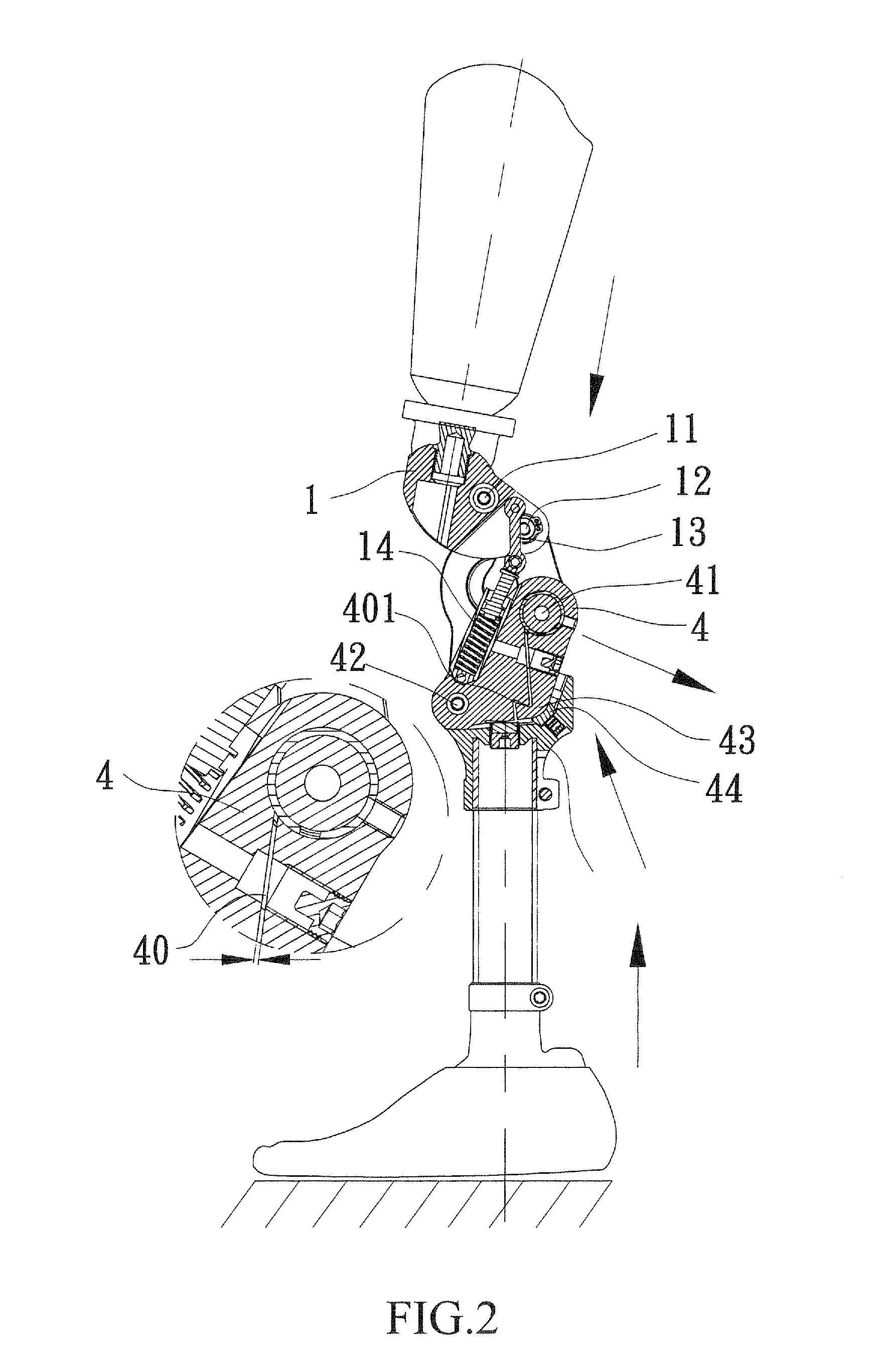
[0005]In view of the drawbacks of the conventional four-bar-linkage prosthesis knee joint that are discussed above, the present invention aims to provide a four bar linkage for prosthesis, which comprises a clamp member, whereby when the user of the prosthesis takes an easy standing posture by slightly bending the knee or attempts to shift the gravity center to the artificial limb side, the body weight and a force induced in the lower portion of the prosthesis and transmitted upward work together to cause a compression block that is arranged in a rear portion of a joint body to directly depress a clamp back. This makes a ga

Problems solved by technology

However, when the user shifts the gravity center from the natural limb side to the artificial limb side, it is quite easy for the knee joint to make a sudden bending in the clockwise direction, leading to potent

Method used


Image

  • Four-bar-linkage brake-included knee joint
  • Four-bar-linkage brake-included knee joint
  • Four-bar-linkage brake-included knee joint

Examples


Example

[0018]The following descriptions are exemplary embodiments only, and are not intended to limit the scope, applicability or configuration of the invention in any way. Rather, the following description provides a convenient illustration for implementing exemplary embodiments of the invention. Various changes to the described embodiments may be made in the function and arrangement of the elements described without departing from the scope of the invention as set forth in the appended claims.

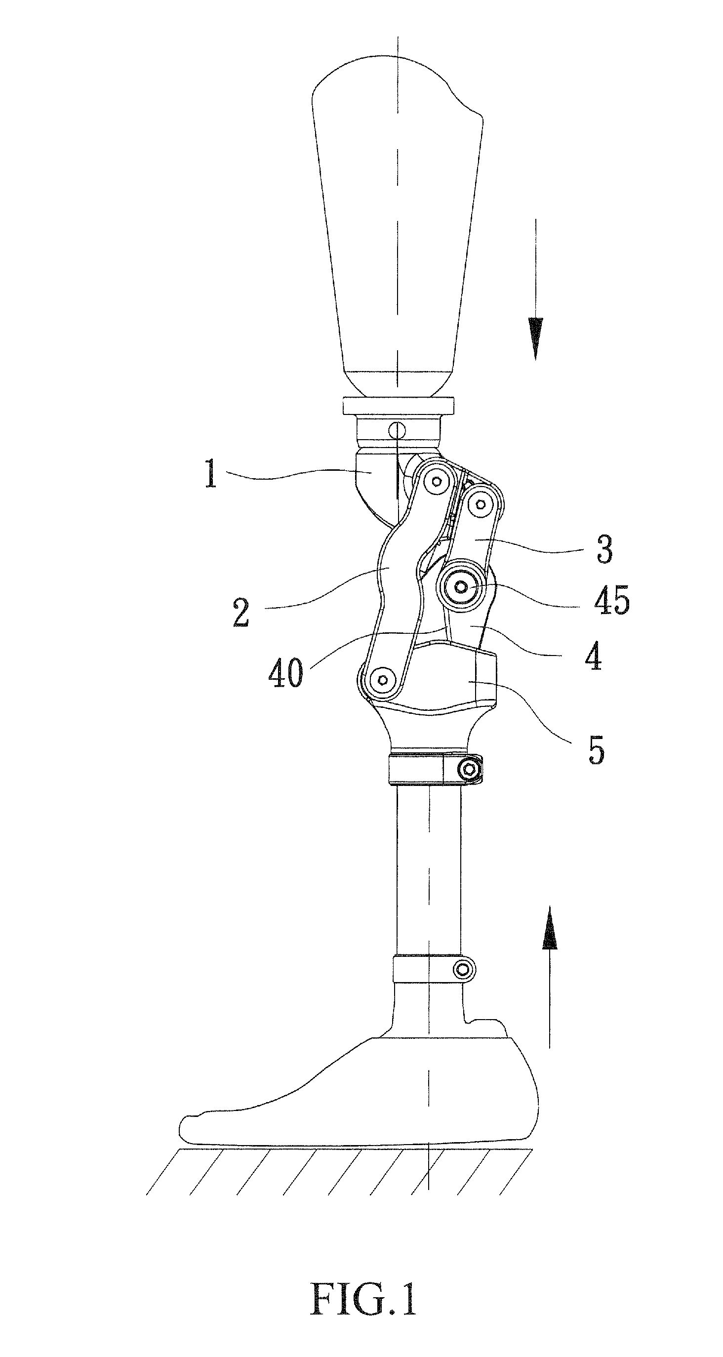
[0019]An explanation of the structure and function of the present invention will be given for a preferred embodiment thereof with reference to the attached drawings in order to provide a more clear illustration of the principle of the present invention. The present invention provides a four-bar-linkage brake-included knee joint, which, as shown in FIGS. 1-6, comprises mainly a knee carriage 1, first links 2, second links 3, a clamp member 4, and a joint body 5.

[0020]As shown in FIGS. 1-6, the knee c...


PUM


Abstract

A four-bar-linkage brake-included knee joint includes a knee carriage, first and second links rotatably coupled to the carriage, and a clamp member coupled to a joint body. The clamp member forms a through hole that receives an axle to couple the second links. A compression block is received in a rear portion of the joint body and is set in engagement with a back side of the clamp member. The clamp member forms a gap extending from the through hole of the clamp member to a bottom of the clamp member. When a heel of a prosthesis that includes the knee joint is put on the ground, a reaction force is induced in the prosthesis that causes the compression block to directly depress the clamp member thereby reducing the gap to have the clamp member tightly clamping the axle and thus preventing the axle from further rotation.

Description

(a) TECHNICAL FIELD OF THE INVENTION[0001]The present invention generally relates to a four-bar-linkage brake-included knee joint, which uses body weight or reaction forces induced by an artificial limb contacting the ground to reduce a gap formed in a clamp member for constraining rotation of axle thereby eliminating the potential risk caused by sudden bending of prosthesis knee joint in a standing or walking condition.(b) DESCRIPTION OF THE PRIOR ART[0002]A good prosthesis knee joint provides different supports to gravity center and associated cushioning. Also, the prosthesis knee joint requires a safety structure to provide protection against potential risk caused by sudden bending of the joint in a walking condition or in a process of changing the location of gravity center.[0003]As shown in FIG. 7 of the attached drawings, a prosthesis user is often capable of steadily hold and support the body weight with the feet in a standing condition where the knee joint does not bend. Wit...

Claims


Application Information

Patent Timeline
IPC IPC(8): A61F2/64A61F2/68
CPCA61F2/644A61F2002/5003A61F2002/5007
Inventor CHENG, CHIA-PAOWU, FU-KUO
Owner KEN DALL ENTERPRISE
Why Eureka
Try Eureka