Plane illumination apparatus and backlight apparatus

a backlight apparatus and illumination apparatus technology, applied in the direction of luminescence, lighting and heating apparatus, instruments, etc., to achieve the effect of suppressing the generation of brightness unevenness

Active Publication Date: 2016-10-18
DAI NIPPON PRINTING CO LTD
View PDF22 Cites 3 Cited by
  • Summary
  • Abstract
  • Description
  • Claims
  • Application Information

AI Technical Summary

Benefits of technology

[0011]The inventors have extensively researched under consideration of the points discussed above, and as a result, the inventors have contrived the invention regarding a plane illumination apparatus and a backlight apparatus which illuminate a specific zone repeatedly with coherent light beams that are then diffused and taken out to the outside with speckles made inconspicuous. Moreover, the inventors have proceeded with researches and succeeded in improvement in the illumination apparatus to constantly prevent the generation of a region extremely bright in a specific zone illuminated with coherent light beams. Namely, the purpose of the present invention is to provide a plane illumination apparatus and a backlight apparatus that are capable of making speckles inconspicuous and effectively suppressing the generation of brightness unevenness in a specific zone.
[0019]According to the present invention, it is possible to provide a plane illumination apparatus and a backlight apparatus that are capable of making speckles inconspicuous and effectively suppressing the generation of brightness unevenness in a specific zone.

Problems solved by technology

Not only backlight apparatuses, speckles are problems in a variety of apparatuses having an illumination apparatus for illuminating an illumination zone with coherent light beams.

Method used


Image

  • Plane illumination apparatus and backlight apparatus
  • Plane illumination apparatus and backlight apparatus
  • Plane illumination apparatus and backlight apparatus

Examples


Embodiment Construction

[0029]Hereinafter, embodiments of the present invention will be explained with reference to the drawings. In the accompanying drawings of the present description, in order for simplifying drawings and easy understanding, the scale, the ratio of height to width, etc., are appropriately modified or enlarged.

[0030]A plane illumination apparatus according to an embodiment of the present invention is applicable to a backlight apparatus to be installed into, for example, a liquid crystal panel or the like. However, not necessarily be limited to an application to a backlight apparatus, a plane illumination apparatus according to an embodiment of the present invention can be used as a plane illumination apparatus for illumination at a specific size of plane.

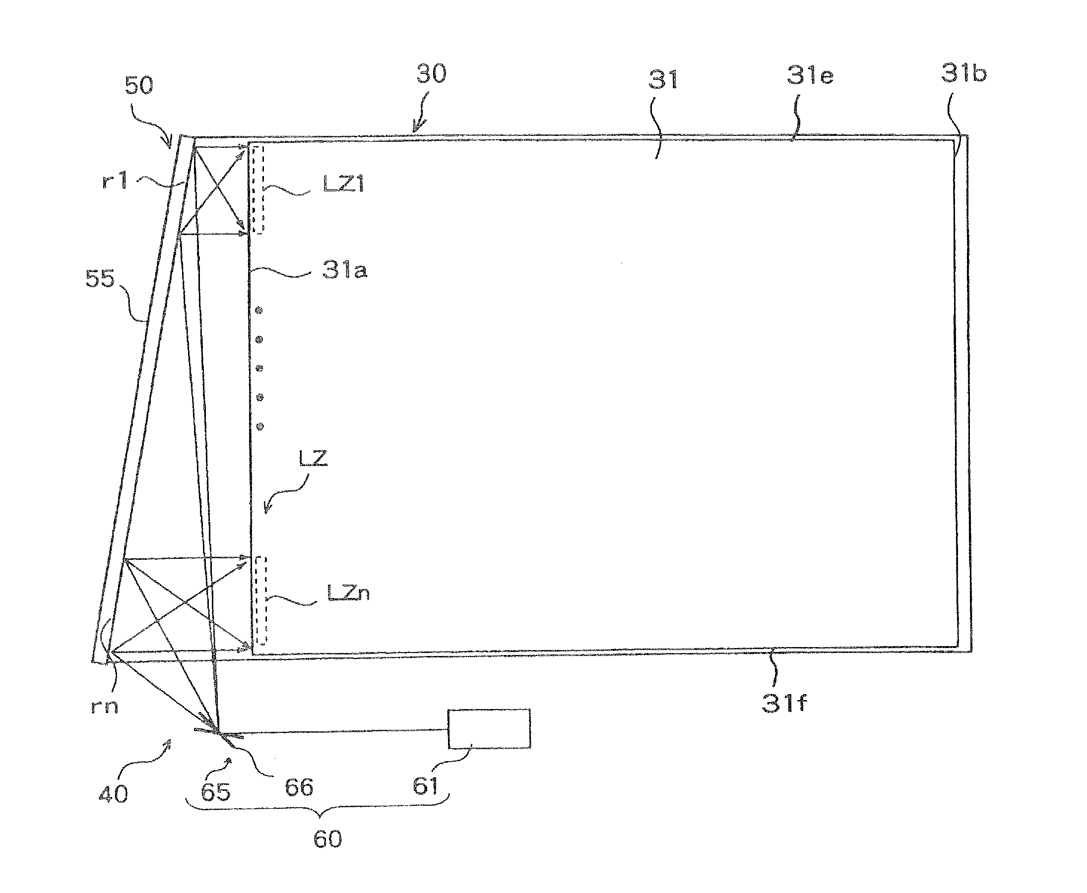
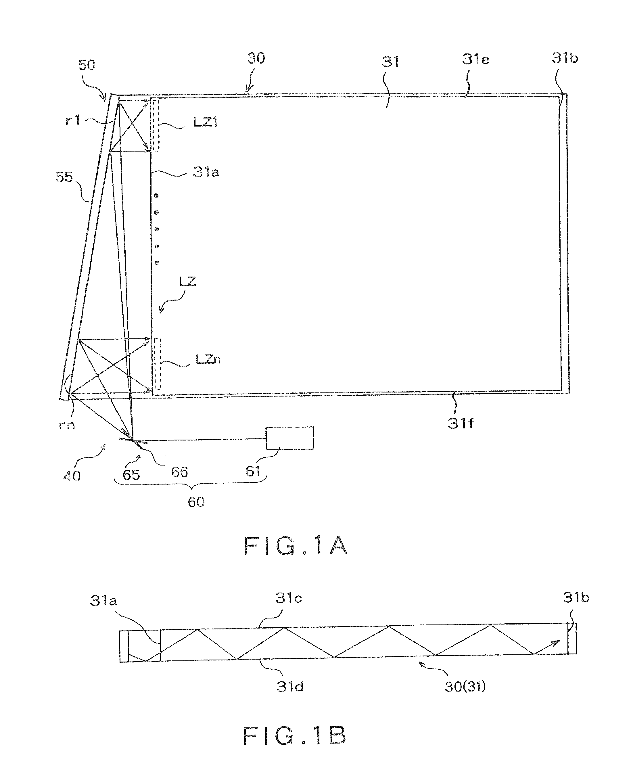
[0031]FIGS. 1A and 1B are views showing a schematic configuration of a plane illumination apparatus according to an embodiment of the present invention. FIG. 1(a) is a plan view and FIG. 1(b) is a sectional view of FIG. 1(a). The plane i...


PUM

PropertyMeasurementUnit
widthaaaaaaaaaa
frequencyaaaaaaaaaa
diffusion angleaaaaaaaaaa

Abstract

A plane illumination apparatus has an optical device, an irradiation unit to irradiate the coherent light beams to the optical device. The irradiation unit makes the coherent light beams scan the surface of the optical device by changing propagation directions of the coherent light beams, the light guide plate comprises a light take-out portion specific zone to take out coherent light beams to outside while making coherent light beams propagate between a first end face on which coherent light beams from the optical device are incident and a second end face that is provided to face the first end face, and the specific zone is provided inside the light take-out portion or along the first end face, or along the second end face.

Description

BACKGROUND OF THE INVENTION[0001]1. Field of the Invention[0002]The present invention relates to a plane illumination apparatus and a backlight apparatus that use a light source for emitting coherent light beams.[0003]2. Description of Related Art[0004]As a backlight apparatus used in liquid crystal panels or the like, a system in which light is incident on an edge of a light guide plate, repeatedly reflected between two opposing surfaces by total reflection, and then taken out by a diffusion device or the like is known. This type of backlight apparatus includes backlight apparatuses using a cold cathode fluorescent lamp as a light source and also, recently, backlight apparatuses using an LED as a light source.[0005]When a cold cathode fluorescent lamp is used, there is a problem in that it is difficult to make a backlight apparatus thin and power consumption increases. When an LED is used, although it is possible to make a backlight apparatus thin, since an LED is a uniform diffusi...

Claims


Application Information

Patent Timeline
Patent Type & Authority Patents(United States)
IPC IPC(8): F21V8/00G02B5/32G03H1/32G02B27/48G02F1/1335G03H1/22
CPCG02B6/0013G02B5/32G02B6/003G02B6/0023G02B6/0031G02B6/0066G02B27/48G03H1/32G02B6/0025G02F1/133615G03H2001/2292F21K2/00F21S2/005G02B6/0001G02F1/1335F21Y2115/10
Inventor KURASHIGE, MAKIOOOYAGI, YASUYUKI
Owner DAI NIPPON PRINTING CO LTD
Why Eureka
Try Eureka