Method for improving the illumination of an illumination region from an illumination device

a technology of illumination device and illumination area, which is applied in the direction of mechanical equipment, lighting and heating equipment, treatment rooms, etc., can solve the problems of inability to work inability to effectively illuminate the illuminated area, and inability to cast shadows inherently within the illuminated area, so as to improve the illumination situation of the illuminated area, the effect of cost-effective and simple manner

Active Publication Date: 2016-11-08
DRAGERWERK AG
View PDF8 Cites 8 Cited by
  • Summary
  • Abstract
  • Description
  • Claims
  • Application Information

AI Technical Summary

Benefits of technology

[0005]An object of the present invention is to eliminate at least one of the above-described drawbacks. In particular, an object of the present invention is to provide an improved illumination situation for the illuminated area in a cost-effective and simple manner.

Problems solved by technology

The drawback of prior-art illuminating devices is that it is necessary to work within the illuminated area.
This causes cast shadows to inherently occur within the illuminated area.
If a body part of the surgeon is located between the illuminating device and the illuminated area, the illuminated area is essentially even darkened completely and the visibility conditions deteriorate.
However, this leads to a great design effort, so that such illuminating devices are especially cost-intensive.
Sufficient space may also be lacking at some sites of use for accommodating such especially large illuminating devices in the first place.
Last but not least, the operability of such especially large illuminating devices has drawbacks.

Method used


Image

  • Method for improving the illumination of an illumination region from an illumination device
  • Method for improving the illumination of an illumination region from an illumination device
  • Method for improving the illumination of an illumination region from an illumination device

Examples


Embodiment Construction

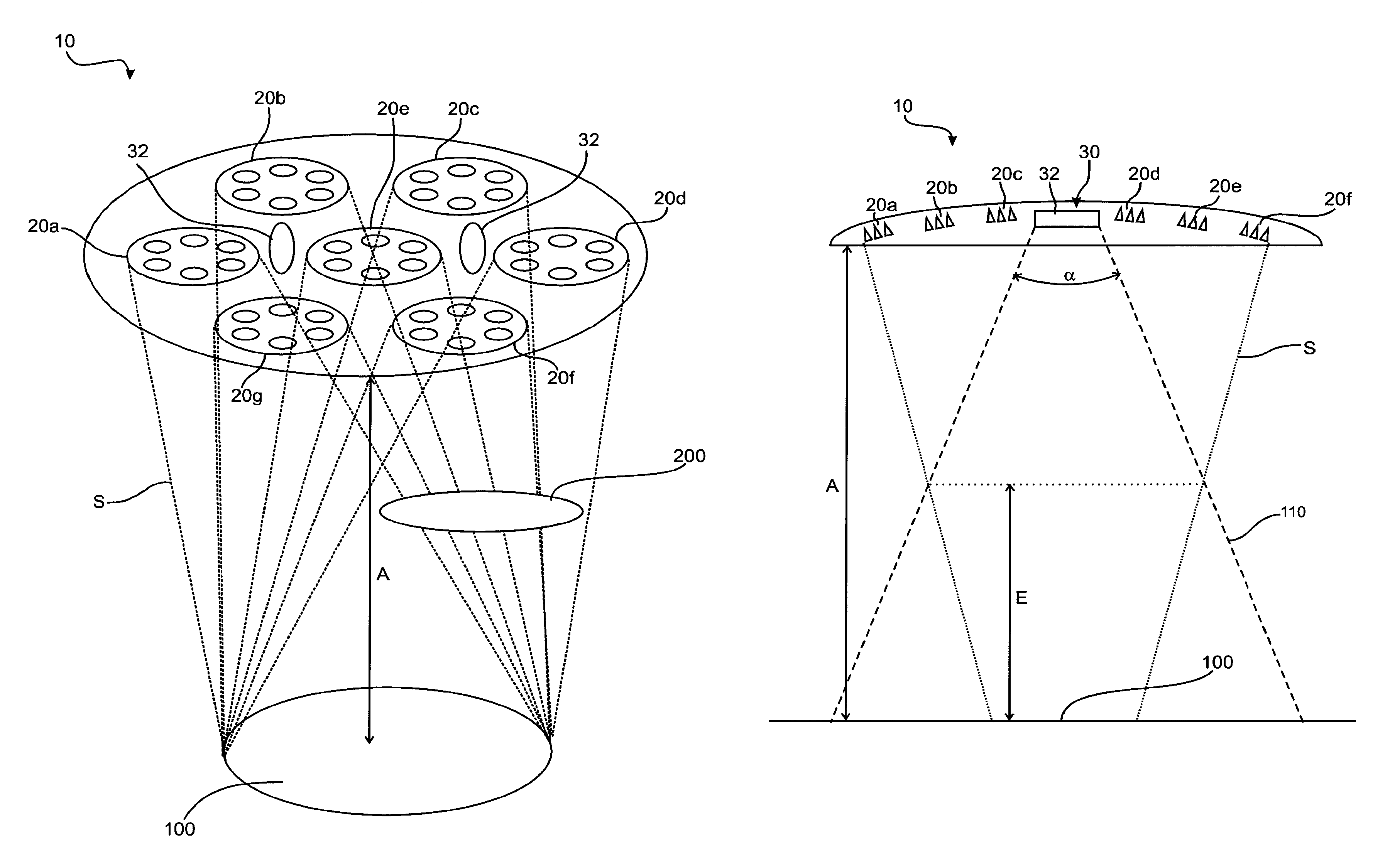
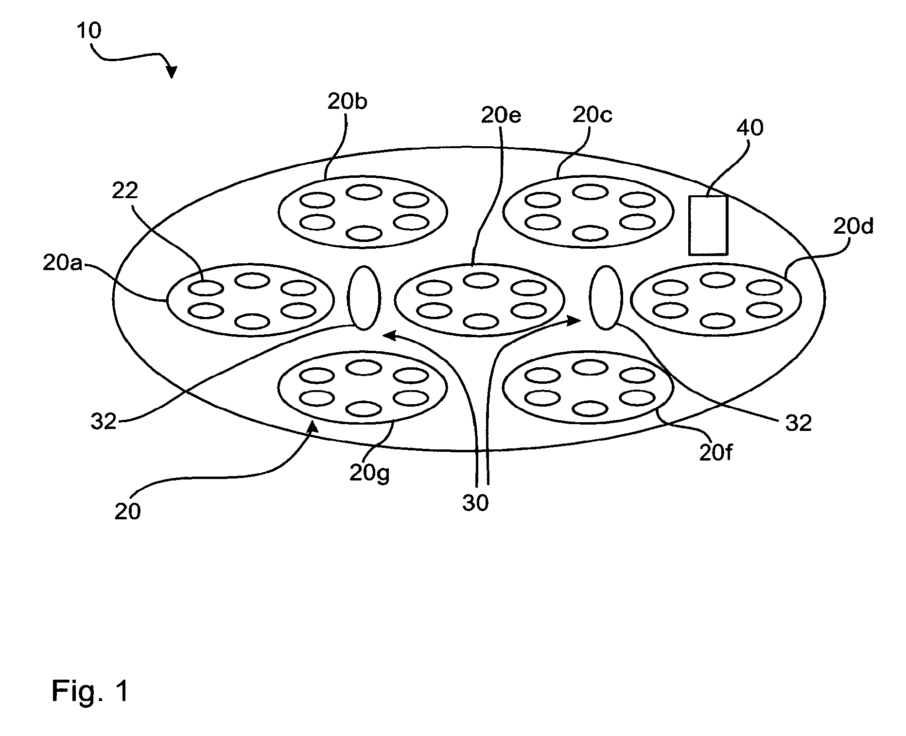
[0043]FIGS. 1 through 3 show a first embodiment of an illuminating device 10 according to the present invention. This has a plurality of light modules 20, namely, the light modules 20a through 20g. Moreover, two sensor means 32 are provided as a sensor device 30. A control unit 40 is also formed, which is in signal-communicating contact with the sensor device 30, The sensor means 32 are designed for detecting depth information.

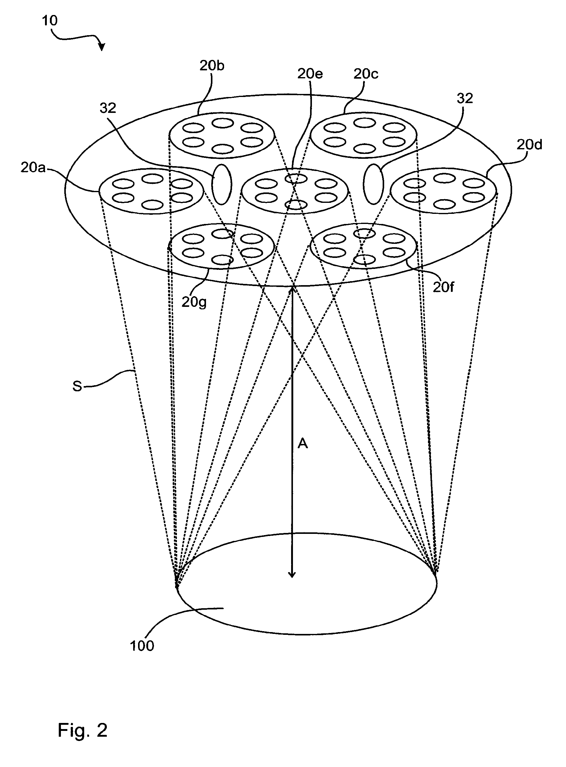
[0044]FIG. 2 shows a possible arrangement of an illuminating device 10, The individual light modules 20 (20a through 20g) produce an illuminated area 100, which is arranged at a working distance A from the illuminating device 10. Some beam paths S for the light modules 20 are schematically indicated. Thus, all beam paths overlap within the illuminated areas 100 and generate there as a sum the desired overall intensity in this illuminated area 100. It is, however, also possible within the framework of the present invention that the beam paths overlap only partl...


PUM


Abstract

A method for improving the illumination of an illumination region (100), in particular of an operation region, from an illumination device (10), includes at least two light modules (20) and at least one sensor device (30) for detecting depth information. The method includes the steps of monitoring a monitored volume (110) between the light modules (20) and the illumination region (100), identifying the position and the geometry as object data of at least one object (200) within the monitored volume (110), comparing the identified object data with beam paths (S) from the light modules (20), and modifying the light intensity of at least one light module (20) on the basis of the comparison between the identified object data with beam paths (S) from the light modules (20).

Description

CROSS REFERENCE TO RELATED APPLICATIONS[0001]This application is a U.S. National Phase Application of International Application PCT / EP2014 / 001688 filed Jun. 20, 2014 and claims the benefit of priority under 35 U.S.C. §119 of German Patent Application 10 2013 012 231.7 filed Jul. 23, 2013 the entire contents of which are incorporated herein by reference.FIELD OF THE INVENTION[0002]The present invention pertains to a method for improving the illumination of an illuminated area of an illuminating device, to a corresponding illuminating device as well as to the use of such an illuminating device for a lighting fixture of an operating room.BACKGROUND OF THE INVENTION[0003]It is known that illuminating devices are used, e.g., for lighting fixtures of operating rooms. The illuminating device has for this at least two light modules, which are capable of emitting light. This emitted light is used to make available the brightening of an illuminated area. This area is especially the operating ...

Claims


Application Information

Patent Timeline
Patent Type & Authority Patents(United States)
IPC IPC(8): H05B37/02F21V23/04H05B33/08F21W131/205H05B44/00
CPCH05B37/0227A61B90/30F21V23/0471F21W2131/205H05B33/0815A61B90/36H05B47/115H05B47/125Y02B20/40
Inventor ELFRING, ROBERTFRANZ, FRANKKRETSCHMANN, HANNOSCHLICHTING, STEFAN
Owner DRAGERWERK AG
Why Eureka
Try Eureka