Eureka AIR delivers breakthrough ideas for toughest innovation challenges, trusted by R&D personnel around the world.

Control system for controlling a process

a control system and process technology, applied in the field of control systems, can solve the problems of high hardware and engineering costs of such control systems known from prior art, the control system cannot be used to a limited extent, and the human and/or material assets are at risk, so as to achieve cost-effective and simple manner, improve the diagnostics of an error function, and save costs

Inactive Publication Date: 2012-05-17
PHOENIX CONTACT GMBH & CO KG
View PDF5 Cites 1 Cited by
  • Summary
  • Abstract
  • Description
  • Claims
  • Application Information

AI Technical Summary

Benefits of technology

[0007]The invention is based on the objective to provide a control system, a control device, as well as a method for controlling a process, which allows in a particularly simple and beneficial manner a particularly safe control of the process.
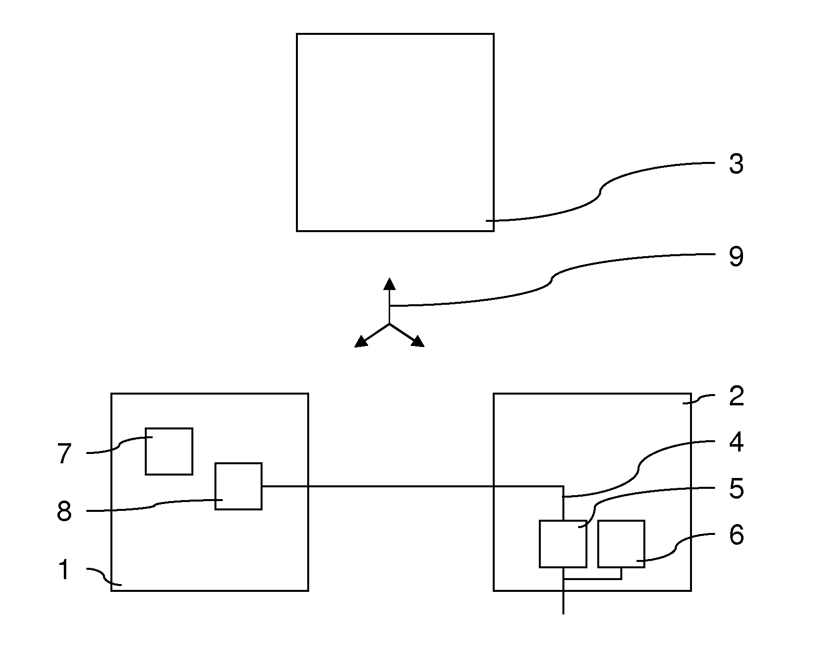
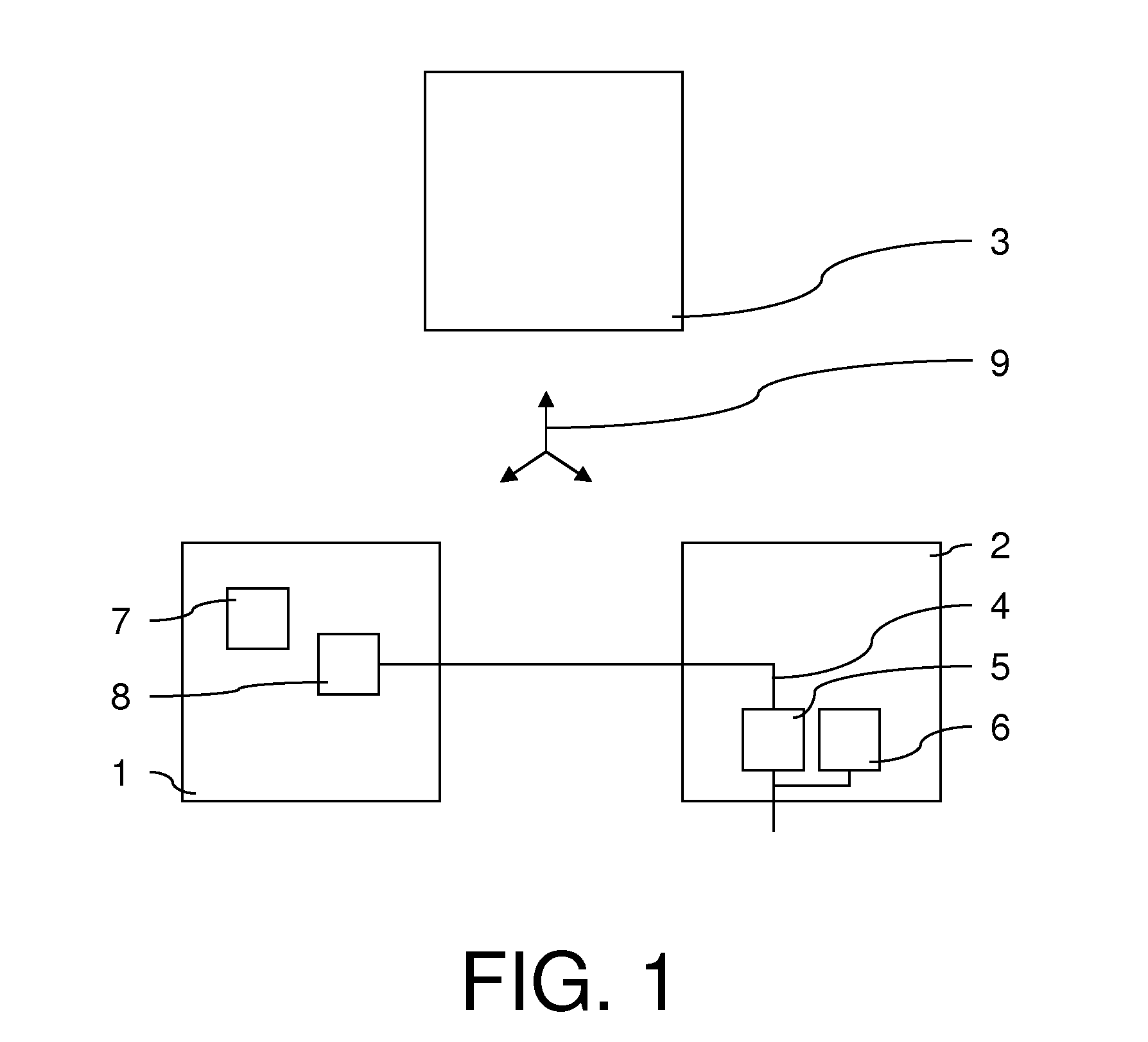
[0011]The control system according to the invention allows therefore a simple and clean separation between the standard technology, such as the outlet module, thus the components of the control system, which are not subject to the above-mentioned safety standards for safety-relevant processes, and the safety technology, such as the safety module, thus the components of the control system subject to the above-mentioned safety standards for safety-relevant processes, so that the construction size of the components used in the control system according to the invention compared to known components of prior art can be reduced. Due to the fact that the safety module, which is embodied preferably according to the above-mentioned safety standards, fulfills the requirements to control a safety-relevant process according to the above-mentioned safety standards, the control system according to the invention also fulfills the requirements of the aforementioned safety standards.
[0015]The control system according to the invention therefore allows the monitoring of a signal for controlling a process such that errors in the output of a signal, such as, for example, a short in the optocoupler of the output module, can be detected in a simple and secure fashion by shorting the electronic component in the output module or a cross fault of an output and / or an actuator connected to said output, and in case of a difference between such a detected actual status from the target status the process can be transferred into a safe mode.
[0019]In principle, the communication between the safety module, the output module, and the control and / or the secure control can occur arbitrarily. According to another preferred embodiment of the invention it is provided, though, that a field bus is provided for the communication between the safety module, the output module, and the control and / or the secure control. The field bus is preferably embodied as a field bus known from prior art, such as interbus, profibus, or profinet. Due to the fact that the detected actual status is transmitted between the safety module and the output module, thus no secure data is transmitted between the safety module and the output module, a cost-effective and simple implementation of the control system can occur, for example, via a field bus known from prior art.
[0021]According to the invention, in this way a control device is provided to control a process, particularly a safety-relevant process, which allows in a particularly simple and cost-effective manner by separating the components designed according to the above-mentioned safety standards, such as the safety module, and by standard components, such as the output module, a reliable detection of error functions or error statuses when issuing the secure signal, and in case of an error function or an error status transfers the process into a safe mode.
[0026]According to the invention, in this way a method is provided to control a process, particularly a safety-relevant process, which in a cost-effective and simple manner allows a transfer of the process into a safe mode, particularly when there is a difference between the actual status of the secure signal issued and the target status. The method according to the invention allows an improved diagnostics of an error function with simultaneous cost savings when controlling a process, with a safety module designed according to the above-mentioned safety standards supplying a “standard” output module known from prior art to control a process with a secure signal such that in case of an error, thus when a difference is detected between the secure signal issued by the output module and detected and the target status, the process is transferred into the safe mode.

Problems solved by technology

Such field bus systems known from prior art offer a multitude of possibilities for controlling the process, however it is frequently problematic to design such field bus systems such that they meet safety-relevant requirements.
In this context, a safety-relevant process is considered particularly a process, which in case of an error occurring leads to a risk for humans and / or material assets, which may not be ignored.
However, the costs for the hardware as well as the engineering expense of such control systems known from prior art are very high.
Furthermore, such control systems can only be used to a limited extent due to insufficient diagnostic possibilities.
Furthermore, in such control systems it is disadvantageous that a cross fault at the safety-relevant outlet and / or a cross fault between outlets that must be supplied by the very same secure outlet module is not detected, and in such a case an arrangement controlled by the control system as well as the operating personnel might be in danger.
Due to the fact that the safety module is implemented according to the requirements of the above-mentioned safety standards error conditions listed in the above-mentioned safety standards can also be detected by the safety module, which then also can lead to a transfer of the process into the safe mode.

Method used


Image

  • Control system for controlling a process
  • Control system for controlling a process

Examples


Embodiment Construction

[0033]The safety module 1, embodied according to the specifications of the safety standards, such as DIN EN 61508, DIN EN 62061, and / or DIN EN ISO 13849, provides a secure signal 4, which in the present case represents a voltage.

[0034]The output module 2, preferably designed similar to an output module for industrial control systems known from prior art, comprises an output 5 for issuing a secure signal 4 to control the process. Furthermore, the output module 2 comprises a means for the detection 6 of an actual status of the output 5. A diagnostic signal can be yielded from the means for detection 6, which reflects the actual status of the output 5.

[0035]The safety module 1 further comprises a comparison means 7 to compare the actual status with the target status as well as a shut-off means 8 for transferring the process into a safe mode. According to the preferred exemplary embodiment of the invention it is provided that the switching means 8 transfers the process into a safe mode ...


PUM


Abstract

The invention relates to a control system for controlling a process, comprising a safety module (1) and an output module (2), wherein the safety module (1) provides a definite signal (4), the output module (2) has an output (5) for outputting the definite signal (4) to control the process, the output module (2) has a means for reading back (6) an actual state of the output (5), wherein by means of the safety module (1) the actual state read back can be compared with a target state and in the event of a difference between the actual state and the target state the process can be brought to a safe state. According to the invention, a control system for controlling a process, in particular for controlling a safety-related process, that can be used in very cost-effective way in particular for safety-related applications is thereby specified. The invention further relates to a control device and a method for controlling a process

Description

FIELD OF TECHNOLOGY[0001]The invention relates to a control system as well as a control device for controlling a process with a safety module and an output module. Furthermore, the invention relates to a method for controlling a process with a safety module and an output module.BACKGROUND[0002]Control systems for controlling a process, particularly a safety-relevant process, are of superior importance in many fields of applications, such as in automation technology. Such control systems, which can also be implemented as field bus systems, typically comprise a plurality of signal units or bus participants connected to the processes to be controlled, and generally comprise a bus master, which controls a frame-based communication via a so-called field bus telegram via the field bus. Such field bus systems known from prior art offer a multitude of possibilities for controlling the process, however it is frequently problematic to design such field bus systems such that they meet safety-r...

Claims


Application Information

Patent Timeline
Patent Type & Authority Applications(United States)
IPC IPC(8): G05B9/02
CPCG05B9/02G05B2219/14012G05B2219/1185G05B19/058
Inventor OSTER, VIKTOR
Owner PHOENIX CONTACT GMBH & CO KG
Why Eureka
Eureka Blog
Learn More