Fluorescent endoscope system enabling simultaneous achievement of normal light observation based on reflected light and fluorescence observation based on light with wavelengths in infrared spectrum

a fluorescence endoscope and fluorescence technology, applied in the field of fluorescence endoscope system, can solve the problems of poor transmittance of light with short wavelengths relative to living tissues, and it is difficult to distinguish self-fluorescence from fluorescence emanating from fluorescent substances, so as to prevent a lesion and good transmittance

Inactive Publication Date: 2007-02-20
OLYMPUS CORP
View PDF31 Cites 107 Cited by
  • Summary
  • Abstract
  • Description
  • Claims
  • Application Information

AI Technical Summary

Benefits of technology

[0012]The first object of the present invention is to provide a fluorescent endoscope system enabling observation of a fluorescent substance that is excited to fluoresce by means of light with wavelengths in an infrared spectrum exhibiting good transmittance relative to a living tissue, such as, an antibody labeled by indocyanine green, capable of nullifying the influence of self-fluorescence, and capable of preventing a lesion in a deep subcutaneous region from being missed.
[0013]The second object of the present invention is to provide a fluorescent endoscope system in which since a reflected-light image depicted by reflected light and a fluorescence image can be produced simultaneously, there is no difference in time between the images, which enables easy diagnose of a lesion, and of which endoscope can be oriented easily.

Problems solved by technology

Unless an apparatus exhibiting high spectroscopic precision such as a spectrometer is employed, it is hard to distinguish self-fluorescence from fluorescence emanating from a fluorescent substance.
The transmittance of light with short wavelengths relative to a living tissue is so poor that a system using hematoporphyrin to be excited by light with short wavelengths may miss the presence of a substance fluorescing in a deep subcutaneous region.

Method used


Image

  • Fluorescent endoscope system enabling simultaneous achievement of normal light observation based on reflected light and fluorescence observation based on light with wavelengths in infrared spectrum
  • Fluorescent endoscope system enabling simultaneous achievement of normal light observation based on reflected light and fluorescence observation based on light with wavelengths in infrared spectrum
  • Fluorescent endoscope system enabling simultaneous achievement of normal light observation based on reflected light and fluorescence observation based on light with wavelengths in infrared spectrum

Examples


first embodiment

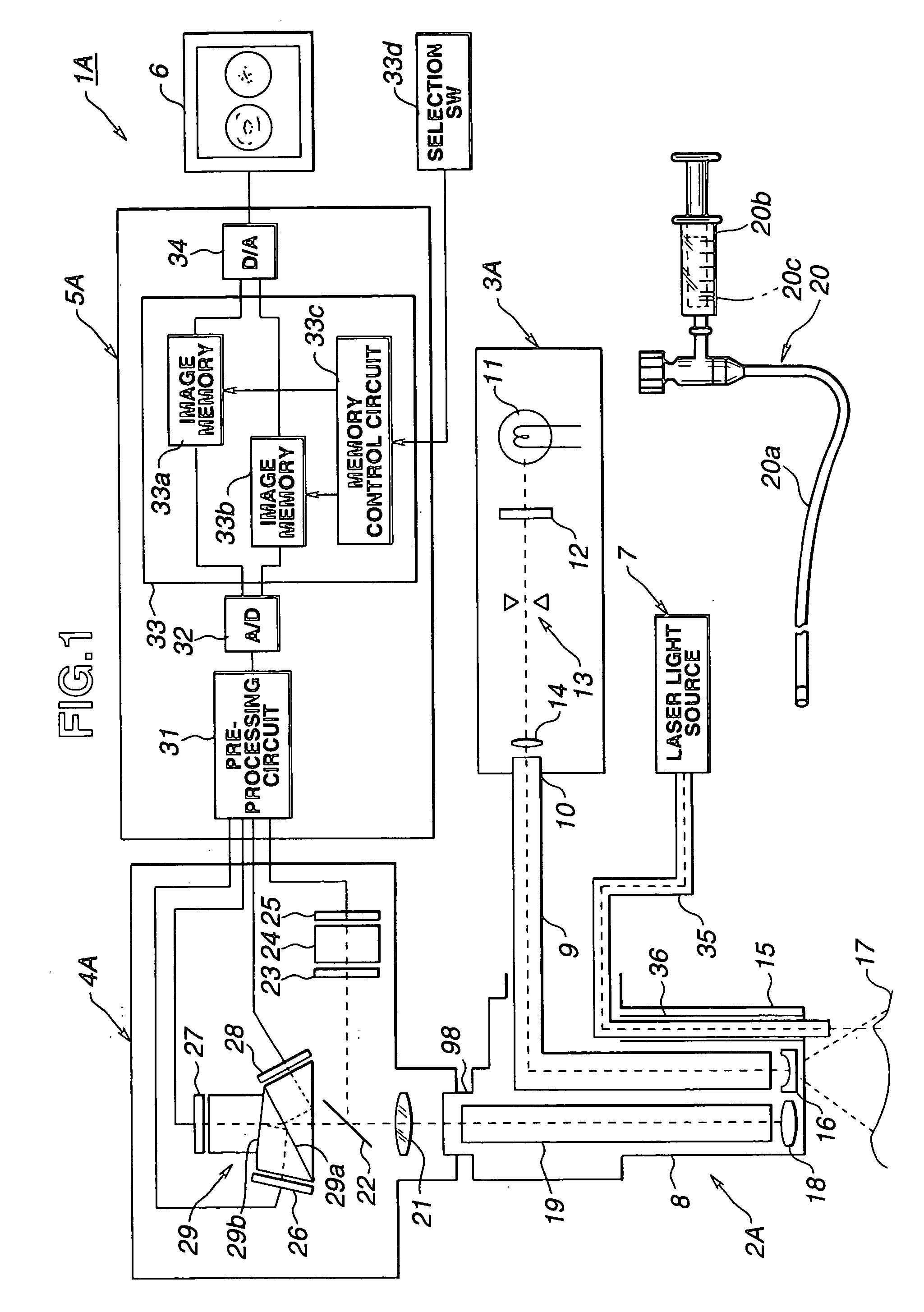
[0088]As shown in FIG. 1, a fluorescent endoscope system 1A in accordance with the present invention comprises an endoscope 2A to be inserted into a body cavity for observation or diagnosis of the inside of the body cavity, a light source apparatus 3A for emitting light for observation and for excitation, a camera head 4A mounted on the endoscope 2A and having an imaging means therein, a processor 5A for processing a signal sent from the imaging means, a monitor 6 for displaying an image, a laser light source 7 for irradiating laser light for treatment, and an administration instrument 20 for use in administering a fluorescent substance into a living body through a forceps channel 36 in the endoscope 2A.

[0089]In this embodiment, an electronic endoscope having an imaging means is realized with a camera-mounted endoscope formed by mounting the freely attachable and detachable camera head 4A on an eyepiece unit 98 of the optical endoscope 2A.

[0090]The endoscope 2A has an elongated flex...

second embodiment

[0144]Next, the present invention will be described. An object of this embodiment is to provide a fluorescent endoscope system capable of producing a visible light image and an infrared fluorescence image depicted by fluorescence emanating from an antibody labeled by indocyanine green, which give different visions of an object attained with no time difference between them, and capable of being realized by adopting a relatively compact imaging system.

[0145]This embodiment is configured similarly to the first embodiment. A difference will be described mainly. The same reference numerals will be assigned to components having similar functions. The description of the components will be omitted.

[0146]A fluorescent endoscope system 1B in accordance with the second embodiment shown in FIG. 8 is different from the fluorescent endoscope system 1A in the first embodiment in a point that an electronic endoscope 2B to be inserted into a body cavity for observation or the like is substituted for...

third embodiment

[0165]Next, the present invention will be described. An object of this embodiment is to produce a visible light image and an infrared fluorescence image depicted by fluorescence emanating from an antibody labeled by indocyanine green, which express the states of objects attained with a very small time difference between them.

[0166]The third embodiment is configured similarly to the first embodiment. Only a difference will be described mainly. The same reference numerals will be assigned to components having similar functions. The description of the components will be omitted.

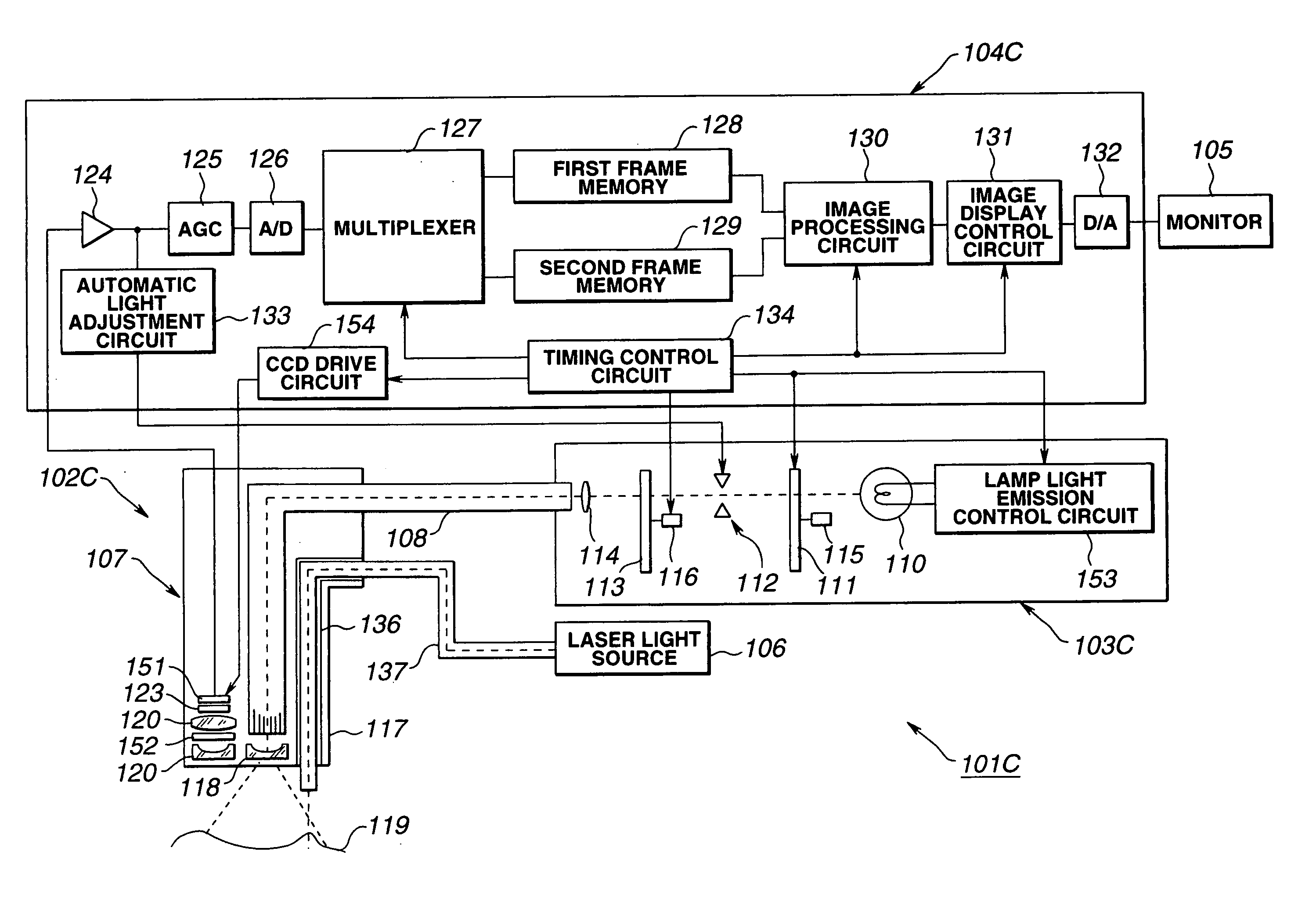
[0167]As shown in FIG. 11, a fluorescent endoscope system IC in accordance with the third embodiment is different from the fluorescent endoscope system 1A in the first embodiment shown in FIG. 1 in a point that a light source apparatus 3B is substituted for the light source apparatus 3A and a camera head 4B is substituted for the camera head 4A.

[0168]The light source apparatus 3B has an RGB rotary filter 41 for ...


PUM


Abstract

A visible light spectrum and a fluorescent light spectrum are received by a variable gain solid state imaging device provided to an endoscope. The variable gain solid state imaging device can be said to lower amplification levels for easily observed visible light spectrum, and higher amplification levels for low intensity fluorescent light spectrum observation. By varying the gain of the imaging device with the different spectrums, an object observed with the endoscope is displayed with approximately similar brightness in each white spectrum. A controller coupled to endoscope system switches different light spectrum to irradiate the observed object, while controlling amplification of the image device. The endoscope provides enhanced image detail to improve diagnosis and treatment of observed abnormal objects.

Description

CROSS-REFERENCE TO RELATED APPLICATIONS[0001]This is a continuation of U.S. patent application Ser. No. 09 / 533,366, filed Mar. 22, 2000, now abandoned which is a divisional of U.S. patent application Ser. No. 08 / 974,531, filed Nov. 19, 1997 now U.S. Pat. No. 6,293,911 of in the name of Katsuichi Imaizumi et al. and entitled FLUORESCENT ENDOSCOPE SYSTEM ENABLING SIMULTANEOUS ACHIEVEMENT OF NORMAL LIGHT OBSERVATION BASED ON REFLECTED LIGHT AND FLUORESCENCE OBSERVATION BASED ON LIGHT WITH WAVELENGTHS IN INFRARED SPECTRUM.BACKGROUND OF THE INVENTION[0002]1. Field of the Invention[0003]The present invention relates to a fluorescent endoscope system for simultaneously producing a reflected-light image depicted by reflected light with wavelengths in the visible spectrum and a fluorescence image depicted by infrared radiation.[0004]2. Description of the Related Art[0005]In recent years, an endoscope of which insertional part is inserted into a body cavity for the purpose of observing the al...

Claims


Application Information

Patent Timeline
Patent Type & Authority Patents(United States)
IPC IPC(8): A61B1/045A61B1/05A61B1/04A61B5/00
CPCA61B1/00009A61B1/00186A61B1/04A61B1/043A61B1/0005A61B1/0646A61B5/0071A61B5/0084A61B1/0638A61B1/000095A61B1/046A61B1/0655
Inventor IMAIZUMI, KATSUICHINAKAMURA, KAZUNARI
Owner OLYMPUS CORP
Why Eureka
Try Eureka