Biosensors

a biosensor and sensor technology, applied in the field of biosensors, can solve the problems of difficult to maintain a dry state inside, complex packaging steps, and high cost, and achieve the effect of excellent sealing ability

Inactive Publication Date: 2005-11-10
NAT INST OF ADVANCED IND SCI & TECH
View PDF12 Cites 89 Cited by
  • Summary
  • Abstract
  • Description
  • Claims
  • Application Information

AI Technical Summary

Benefits of technology

[0015] Thus, a second objective of the present invention is to provide biosensors that allow simultaneous measurement of multiple items using a reduced amount of sample solution, in which the sample solution supplied to a sample-feeding path to eliminate the influence of at least one other biosensor reagent; and to provide methods for measuring test compounds using these biosensors that simultaneously measure multiple items.
[0016] A first invention described herein was made in view of the first objective. By adopting a biosensor structure wherein a sample-inlet port and air-discharge port are exposed as a cross section of the sample-feeding path, achieved by cutting part of the biosensor structure when ready for use, the present inventors discovered biosensors which include a sealed reaction-detecting section comprising at least one set of electrodes and a sealed sample-feeding path, wherein the biosensors enable the reaction-detecting section to be completely sealed prior to use, have excellent sealing ability, and can preserve the inner environment in a preferred state through the use of a desiccant or the like as needed. The present inventors thus completed the present invention.

Problems solved by technology

In conventional systems, bottle container systems are first problematic in that they cannot maintain a dry state inside, due to repeated opening and closing.
In addition, since systems that package biosensors in containers use bulky containers compared to the size of the biosensor, they are problematic in that the packaging step is complex and requires lots of materials.
Furthermore, although systems which package single biosensors by thermal compression of the biosensor between two films can shield ultraviolet rays and maintain a dry state through use of a desiccant, they cannot eliminate the influence of heat and oxidation, and opening the package can be problematic.
Conventional biosensors for simultaneously measuring multiple items are problematic in that sample solutions supplied to the sample-feeding path are affected by at least one biosensor reagent.
In such cases, however, sample solution adheres to the edges of the holes used as sample-inlet ports when that sample solution was supplied to the biosensor feeding path, resulting in the use of sample solution in an amount greater than the inner volume of the sample-feeding path.

Method used


Image

  • Biosensors
  • Biosensors
  • Biosensors

Examples


example 1

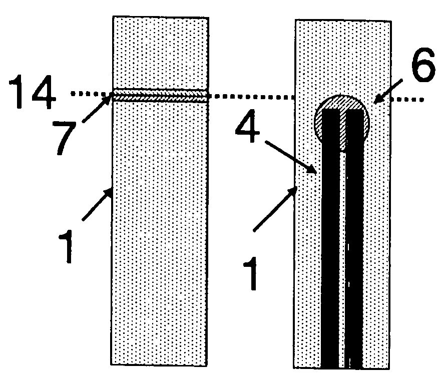
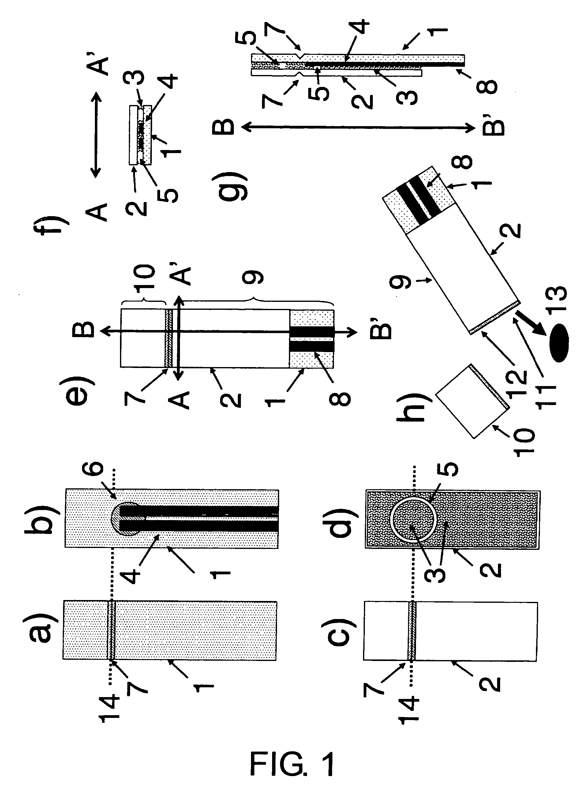
[0417]FIG. 1 shows a representative example of the biosensors of the present invention. FIG. 1 is an example of a biosensor of the present invention in which a cross section of sensor portion 10 appears on cutting the sealed cap portion that does not include an electrode, where the cross section of the sample-feeding path simultaneously forms a sample-inlet port and air-discharge port and is exposed to the outside for the first time.

[0418]FIG. 1a shows the outside of rectangular substrate 1 of a typical biosensor. On top of substrate 1 is a horizontally made V-shaped notch 7, which becomes a cutting plane line. Notch 7 is provided so that sealed cap portion 10 of the biosensor can be cut along broken line 14, by bending or the like, when using the biosensor.

[0419]FIG. 1b shows the inside of substrate 1. Both pattern 4, which includes a pair of electrodes, and reagent layer 6 are formed along the substrate 1 centerline, on the inside upper surface of the substrate. Pattern 4, which...

example 2

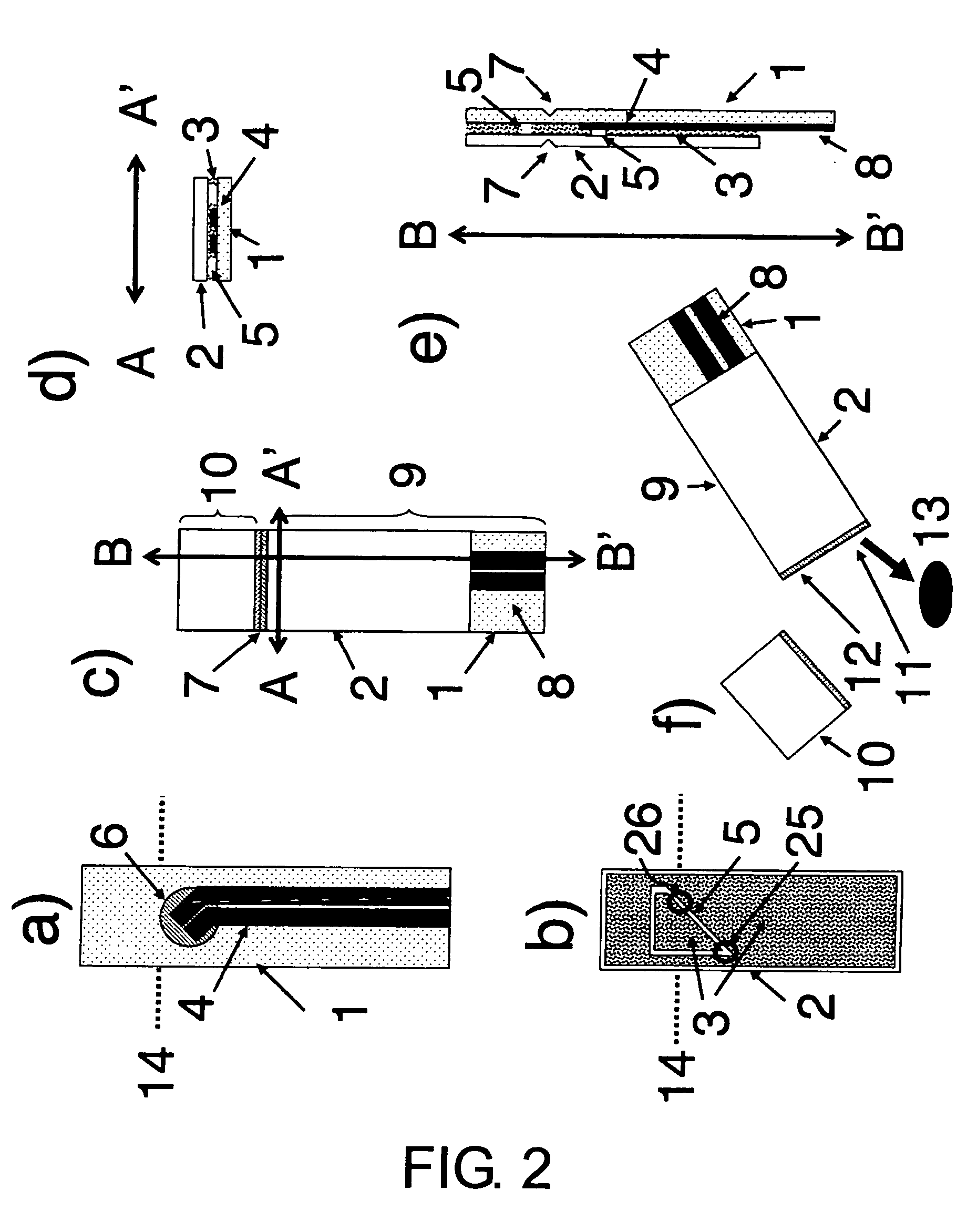
[0427]FIG. 2 shows a biosensor with an outer structure almost identical to that of FIG. 1, and a different inner structure.

[0428] In FIG. 2a, the wiring section, which includes the terminal of pattern 4 comprising electrodes, is located slightly right of the substrate center. The electrode part for detecting the reaction is located diagonally up on the left side. The reagent layer 6 is formed immediately below broken line 14, on the center line of the substrate, i.e., at the same position as shown in FIG. 1a.

[0429]FIG. 2b shows the inner surface of cover 2. On the inside upper surface of cover 2, the spacer layer, as well as a portion 5 inside the spacer layer, which comprises no spacer, are provided in a trapezoid shape, with the acute angle down. FIG. 2c is an example of a structural diagram where the inner surfaces of substrate 1 and cover 2 are overlapped with the top ends aligned, showing a substrate 1 terminal exposed at the bottom. FIG. 8b shows the inner structure of the d...

example 3

[0432]FIG. 3 shows an example of the biosensor structure in FIG. 2, where the reagent-feeding path is curved from part 26, which becomes the sample-inlet port of the sample-feeding path, to the bent portion 25 (when sealed the sample-feeding path is fan-shaped).

[0433] Since the reagent-feeding path is curved, a sample solution can be smoothly supplied to a position past the electrode part that intersects with the sample-feeding path, and stopped at the bent portion of the sample-feeding path further on. Accordingly, the required amount of sample solution can be reduced.

[0434] In this structure, as for FIG. 2, the fan shape that becomes sample-feeding path 5 shown in FIG. 3b has one angle of the fan at the bottom, and is formed in two directions: vertically, and extending upwards in an arc (see also FIG. 8c). This structure is also formed so the part eventually intersects the reaction-detecting section with the electrode near the arc center. Therefore, as shown in FIGS. 3f and 8c, ...


PUM

PropertyMeasurementUnit
depthaaaaaaaaaa
depthaaaaaaaaaa
depthaaaaaaaaaa

Abstract

The biosensors of the present invention comprise an electrically insulating substrate, an electrically insulating cover connected to the substrate via a spacer layer, a reaction-detecting section formed on the substrate at a region sandwiched between the substrate and cover, and comprising at least one set of electrodes, and an external terminal to be connected to the reaction-detecting section, and a sealed sample-feeding path defined between the substrate and cover by the spacer layer, where the sample-feeding path has a portion intersecting the electrodes, as well as a cutting plane line provided at an outermost surface of the substrate or cover, which is a boundary between a sensor portion comprising electrodes and a sealed cap portion which does not comprise electrodes, and the cutting plane line is present at a position where, when the sealed cap portion is cut along the cutting plane line, the cut surface does not cross the electrodes and does cross the sample-feeding path, so that a sample-inlet port and an air-discharge port leading from the sample-feeding path are exposed through the cut surface. In addition, the biosensors for simultaneously measuring multiple items of the present invention comprise: a substrate; a cover connected to the substrate via a spacer layer; and a number of biosensor units comprising substrates each containing at least one biosensor unit which comprises a reaction-detecting section including one electrode system and one reagent layer on the substrate, and a sample-feeding path including the reagent layer, wherein each of the biosensor units comprise one reagent layer on one sample-feeding path, a cutting plane line for dividing each of the biosensor unit-comprising substrates is provided at a top surface of the substrate or cover, the cutting plane line and sample-feeding path are placed such that, when the substrate or cover is cut along the cutting plane line, a sample-inlet port for supplying a sample solution is open to a cut surface of each biosensor unit-comprising substrate as a cut port of the sample-feeding path.

Description

FIELD OF THE INVENTION [0001] The present invention relates to biosensors. [0002] More specifically, the present invention relates to biosensors comprising a structure that can keep the inside of a reaction-detecting section airtight until use; packagings thereof; methods for using the same; and devices thereof. [0003] The present invention also relates to biosensors for simultaneously measuring multiple items, methods for using the same, and devices thereof, as well as methods for determining test compounds using the biosensors for simultaneously measuring multiple items. BACKGROUND OF THE INVENTION [0004] To date, modes for packaging disposable sensors by using a container include systems where a number of biosensors are retained in a bottle container, and systems where each individual biosensor is retained in its own container and the opening of the container is thermally compressed using a film (Unexamined Published Japanese Patent Application No. (JP-A) 2000-314711). Dry condit...

Claims


Application Information

Patent Timeline
Patent Type & Authority Applications(United States)
IPC IPC(8): G01N27/26G01N33/487
CPCG01N27/3272
Inventor NAKAMURA, HIDEAKISHINOHARA, SHOUJIGOTOH, MASAOKARUBE, ISAO
Owner NAT INST OF ADVANCED IND SCI & TECH
Why Eureka
Try Eureka