Accurate trigger signal producing method and producing circuit

A trigger signal, precise technology, applied in the direction of electrical components, instruments, power automatic control, etc., can solve the problems of quantization error can not be ignored, quantization error, etc., to achieve the effect of simple structure, improved accuracy, high degree of modularity

Inactive Publication Date: 2008-05-21
NAT UNIV OF DEFENSE TECH
View PDF0 Cites 19 Cited by
  • Summary
  • Abstract
  • Description
  • Claims
  • Application Information

AI Technical Summary

Problems solved by technology

However, there is a quantization error in the method of querying the local time of the detection node, which is determined by the execution time of the process of querying the local time twice in a row. When a trigger signal with higher accuracy is required, this quantization error cannot be ignored.

Method used


Image

  • Accurate trigger signal producing method and producing circuit
  • Accurate trigger signal producing method and producing circuit
  • Accurate trigger signal producing method and producing circuit

Examples


Embodiment Construction

[0050] The present invention will be described in further detail below in conjunction with the accompanying drawings and specific embodiments.

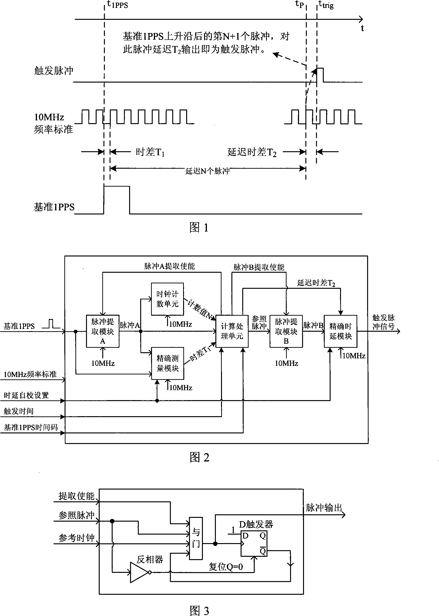
[0051] As shown in Figure 1, at t trig Accurately generate trigger pulse signals at all times. It is difficult to guarantee accurate t trig A trigger pulse is generated every moment. The basic idea of ​​the present invention is to accurately calculate the delayed time difference T2 by accurately measuring the time difference T1, and then output the N+1th pulse signal of the 10MHz frequency reference after the rising edge of the reference second pulse and accurately delay it for T2 , so as to ensure the accuracy of the moment when the trigger pulse signal is generated. Using the delay line method to adjust the time difference T 1 Perform secondary measurement and accurately delay the time difference T2 of the pulse signal. Under the condition of using a 10MHz frequency reference, the accuracy of the moment when the trigger pulse sig...


PUM


Abstract

The present invention provides an accurate trigger signal generating method and a generating circuit thereof. The steps are as follows: Step 1, an external basic pulsing signal and a standard clock signal are accessed; the first pulse of a standard clock after the basic pulsing signal rising edge abstracted and a measuring pulse A is exported outward; Step 2, a clock counting unit counts a 10MHz clock taking the pulse A as the starting point; the time interval T1 of the measuring pulse A and a 10MHz frequency standard signal is measured; Step 3, a calculation and treatment unit works out a delay time difference T2 according to an external basic 1PPS time code t< 1PPS >, a trigger time t< trig >, a counting value N and the time interval T1 and generates a reference pulse signal; Step 4,the first pulse B of a standard clock after the reference pulsing signal rising edge abstracted; Step 5 the pulse B is delayed by the time difference T2 and export outward, which generates an accurate trigger pulsing signal. Based on the accurate delay treatment to the basic pulsing signal, the present invention is connected with time frequency standard and realizes that multiple nodes generates the accurate trigger pulsing signal under the uniform time frequency standard.

Description

technical field [0001] The present invention mainly relates to the application field of wide-area measurement and control technology, in particular to a precise trigger signal generation method and a generation circuit for synchronous measurement and collaborative testing in wide-area measurement and control applications, especially suitable for different locations and nodes at the same time Triggering for synchronous measurement and occasions where different nodes conduct collaborative testing according to strict timing relationships, such as distributed data acquisition systems, directional blasting systems, industrial automation systems, and circuits and methods for measuring and controlling each node at a specific time. Background technique [0002] With the rapid development and wide application of distributed wide-area measurement and control technology, in order to realize synchronous testing of different nodes and collaborative testing in accordance with strict timing...

Claims


Application Information

Patent Timeline
Patent Type & Authority Applications(China)
IPC IPC(8): G05B19/00H03L7/06
Inventor 钟小鹏黄飞乔纯捷明德祥杨俊陈建云王跃科
Owner NAT UNIV OF DEFENSE TECH
Why Eureka
Try Eureka