Mobile robot, and control method and program for the same

a robot and mobile technology, applied in the field of mobile robots and control methods and program for the same, can solve the problems of increasing cost, increasing labor hours and time, increasing errors, etc., and achieve the effect of enhancing the accuracy of estimation, facilitating and accurately carrying out estimation, and enhancing the accuracy of travel positions

Inactive Publication Date: 2007-11-29
FUJITSU LTD
View PDF5 Cites 94 Cited by
  • Summary
  • Abstract
  • Description
  • Claims
  • Application Information

AI Technical Summary

Benefits of technology

[0007]In addition, according to the present invention to provide a mobile robot and a control method and program therefor which can readily and accurately estimate the travel position by utilizing an image of a camera.
[0036]According to the present invention, a plurality of candidate positions are set in the vicinity of the current travel position of a mobile robot predicted by dead reckoning using a turn-angle sensor of a wheel, predictive edge images which are composed of edge information and captured when an imaging unit is virtually disposed at each of the candidate positions are generated based on layout information of the environment such as the positions and heights of pillars and walls, the predictive edge images at the candidate positions are compared with an actual edge image which is extraction of edge information from an actual image, and the candidate position of the predictive edge image which is the most similar to it is estimated as the current travel position of the robot. Therefore, merely by storing comparatively simple layout information of the environment describing wall, pillar positions, etc. in advance in the mobile robot, the predictive edge images can be readily generated, the operation of registering the positions of plural types of specified image characteristics in real space in advance is not required, and self-position estimation utilizing camera images can be simply and accurately performed.
[0037]Moreover, when determination of the degree of similarity by comparison between the predictive edge images and the actual edge image is evaluated by correlation values of the images, and the candidate position of the predictive edge image at which the correlation value is the maximum is estimated as the travel position, the influence of different details of the predictive edge images and the actual edge image is eliminated, a stable comparison process can be realized, and, furthermore, since it is carried out by correlation calculations of edge information, the calculation amount is reduced and it can be realized by a small device.
[0039]Moreover, the plurality of predictive edge images are generated while changing the image-capturing direction of the imaging unit for each of the candidate positions; therefore, the plurality of predictive edge images of different image-capturing directions are generated at the same candidate position and compared with the actual edge image. Even if the image-capturing direction of the actual image is deviated from the planned travel direction, as long as the predictive edge image of the maximum degree of similarity can be obtained, it is estimated as a correct travel position, and the estimation accuracy of the travel position can be further enhanced.
[0040]Moreover, in generation of the predictive edge images which are generated when the imaging unit is virtually disposed at candidate positions, the generation can be readily and accurately carried out based on the camera parameters of the imaging unit and the three-dimensional coordinates of the layout information.
[0041]Furthermore, the estimation process of the current travel position based on the actual edge image and the plurality of predictive edge images is repeated in a processing cycle of a predetermined travel distance or predetermined movement time; therefore, the estimation accuracy can be enhanced by shortening the processing cycle. The above and other objects, features, and advantages of the present invention will become more apparent from the following detailed description with reference to the drawings.

Problems solved by technology

However, such conventional self-position estimation methods of mobile robots involve the following problems.
First of all, the dead reckoning which estimates the travel position of a mobile robot according to the turning angle of wheels has a problem in accumulation of errors caused by slippage, etc. of the wheels.
The method which utilizes particular marks with which a robot recognizes a position in the environment involves a problem that the particular marks have to be placed in the environment side and cost is increased.
In current circumstances, this registering operation is a man-made operation in which, for example, the characteristics are determined with eyes on site and the positions thereof are measured and registered every time, which involves a problem that massive labor hours and time are required.

Method used


Image

  • Mobile robot, and control method and program for the same
  • Mobile robot, and control method and program for the same
  • Mobile robot, and control method and program for the same

Examples


Embodiment Construction

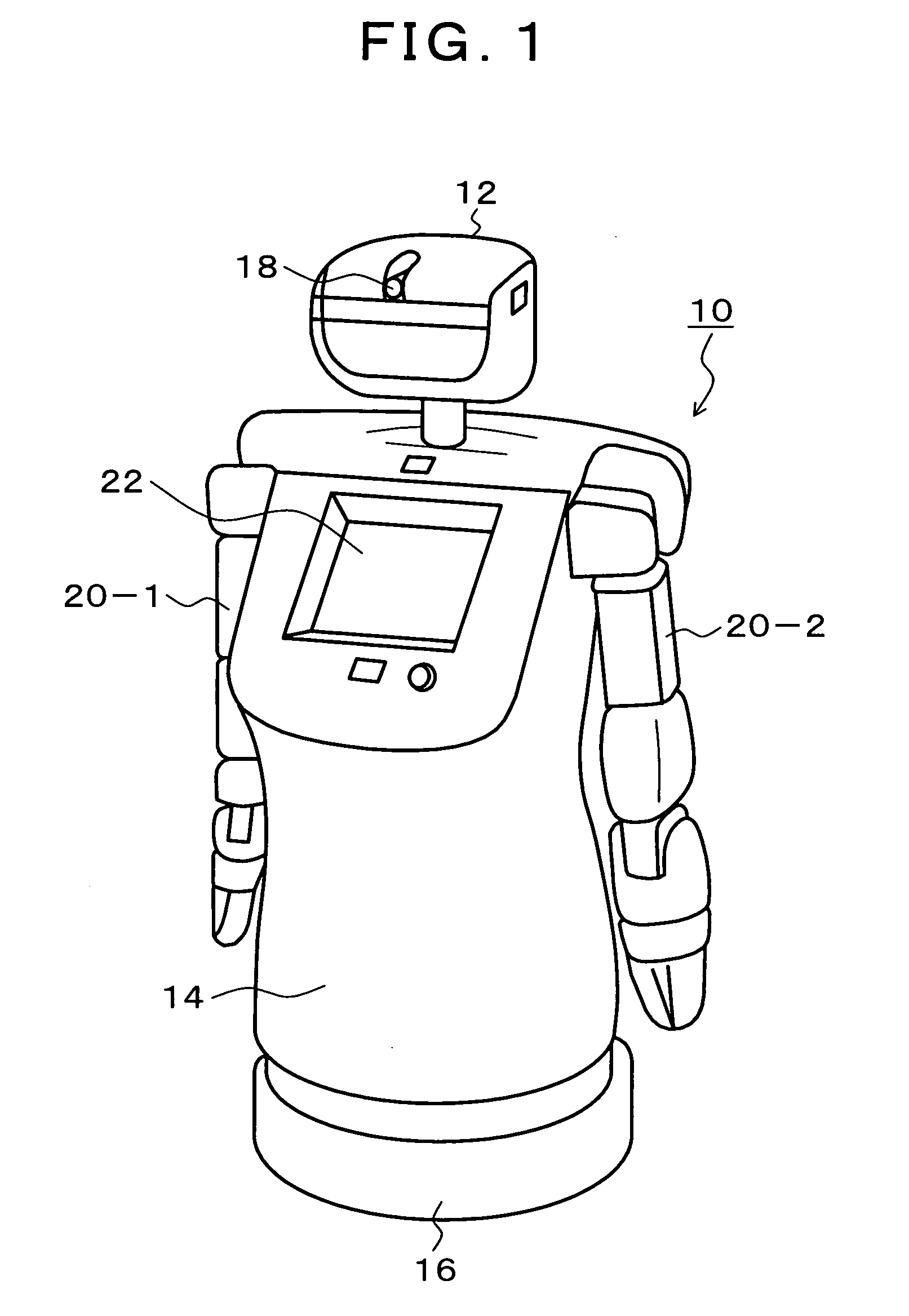
[0051]FIG. 1 is an explanatory diagram of an embodiment of a mobile robot according to the present invention. In FIG. 1, the mobile robot 10 of the present embodiment is composed of five units, that is, a head unit 12, a body 14, a moving unit 16, a left arm 20-1, and a right arm 20-2. The size of the mobile robot 10 is about 60 cm in diameter when horizontally viewed and is about 130 cm in height. The head unit 12 can turn horizontally relative to the body 14, and a camera 18 using imaging devices such as CCDs is directed to the front and attached to the head unit 12. The sight-line direction of the camera 18 can be adjusted by turning the head unit 12. If a plurality of cameras having different sight-line directions are mounted on the head unit 12, the sight directions can be instantly changed by switching the cameras without using a pan / tilt mechanism. In the left arm 20-1 and the right arm 20-2, joints having four degrees of freedom with which hands can be moved to arbitrary pos...


PUM


Abstract

A path planning unit plans a travel path to a destination based on an estimated current travel position and outputs a travel command to a travel control unit to perform travel control so as to follow the travel path. A travel position prediction unit accumulates a travel distance, which is detected by a wheel turning-angle sensor, to the estimated current travel position so as to predict the current travel position. A predictive image generating unit generates a plurality of predictive edge images which are composed of edge information and captured when a camera is virtually disposed at the predicted current travel position and candidate positions in the vicinity of it based on layout information of the environment, and an edge image generating unit generates an actual edge image from the actual image captured by the camera. A position estimation unit compares the edge image with the plurality of predictive edge images, estimates the candidate position of the predictive edge image at which the degree of similarity is the maximum, and updates the travel position of the path planning unit and the travel position prediction unit.

Description

[0001]This application is a priority based on prior application No. JP 2006-146218, filed May 26, 2006, in Japan.BACKGROUND OF THE INVENTION[0002]1. Field of the Invention[0003]The present invention relates to a mobile robot which can carry out various activities such as guiding or leading of people, transportation of objects, and go-round or patrolling and to a control method and a program therefor; and particularly relates to a mobile robot which travels to a destination position while estimating the current travel position from a captured image of a camera and to a control method and a program therefor.[0004]2. Description of the Related Arts[0005]Recently, other than industrial robots operated in manufacturing sites, development of mobile robots which can be adapted to personal uses in, for example, homes, welfare, medical services, and public is underway. Such a robot requires an autonomous mobile function according to a self-position estimation method in which the position of ...

Claims


Application Information

Patent Timeline
Patent Type & Authority Applications(United States)
IPC IPC(8): G06F19/00B25J5/00G05D1/02G06T1/00
CPCG05D1/0272G05D1/0246B25J13/00G01C15/00
Inventor SAWASAKI, NAOYUKI
Owner FUJITSU LTD
Why Eureka
Try Eureka