Radiation imaging device

a radiation imaging and image quality technology, applied in tomography, instruments, nuclear engineering, etc., can solve the problems of reducing image contrast and precision of measured values, deteriorating image quality, etc., and achieves enhanced correction precision, high degree of correction precision, and easy generation

Inactive Publication Date: 2014-07-22
HITACHI LTD
View PDF7 Cites 150 Cited by
  • Summary
  • Abstract
  • Description
  • Claims
  • Application Information

AI Technical Summary

Benefits of technology

[0012]According to the present invention, it is possible to use in the X-ray imaging apparatus, a correction function for the scattered X-ray correction and a correction function for the beam hardening correction, the functions being easily generated and having a high degree of correction precision, and to perform corrections sequentially in appropriate order. Therefore, precision in correction is enhanced, thereby improving the image quality.

Problems solved by technology

On this occasion, scattered X-rays and beam hardening are considered as factors which reduce image contrast and precision of measured values and deteriorate image quality.

Method used


Image

  • Radiation imaging device
  • Radiation imaging device
  • Radiation imaging device

Examples


first embodiment

[0030]Hereinafter, the first embodiment to which the present invention is applied will be explained. In all the drawings for explaining each of the embodiments of the present invention, the constituents having the same function are labeled the same, and tedious explanations shall not be made.

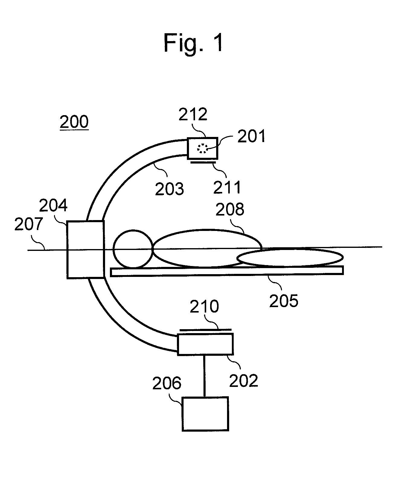
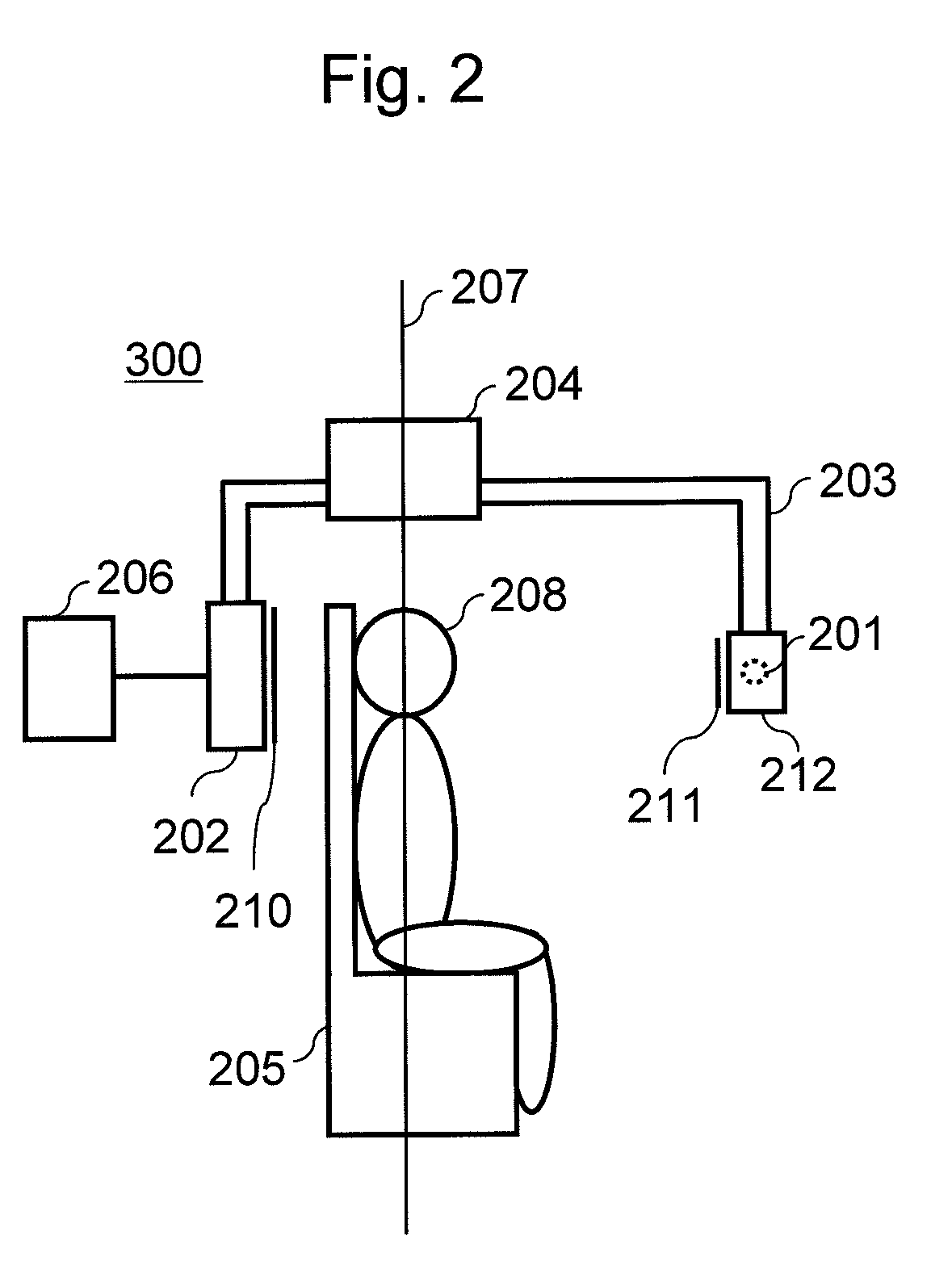
[0031]FIG. 1 is a side view of the X-ray imaging apparatus 200 according to the present embodiment. The X-ray imaging apparatus 200 according to the present embodiment is provided with an X-ray source 201 within an X-ray tube 212, a detector 202, a support 203, a rotation device 204, a subject holder 205, and a control processor 206. The X-ray source 201 and the detector 202 are placed in opposed manner respectively on both ends of the support 203. Here, a C-shaped arm is employed as the support 203, and a bed is employed as the subject holder 205. The rotation device 204 allows the support 203 to rotate around the subject holder 205. Along with the rotation of the support 203, the X-ray source ...

third embodiment

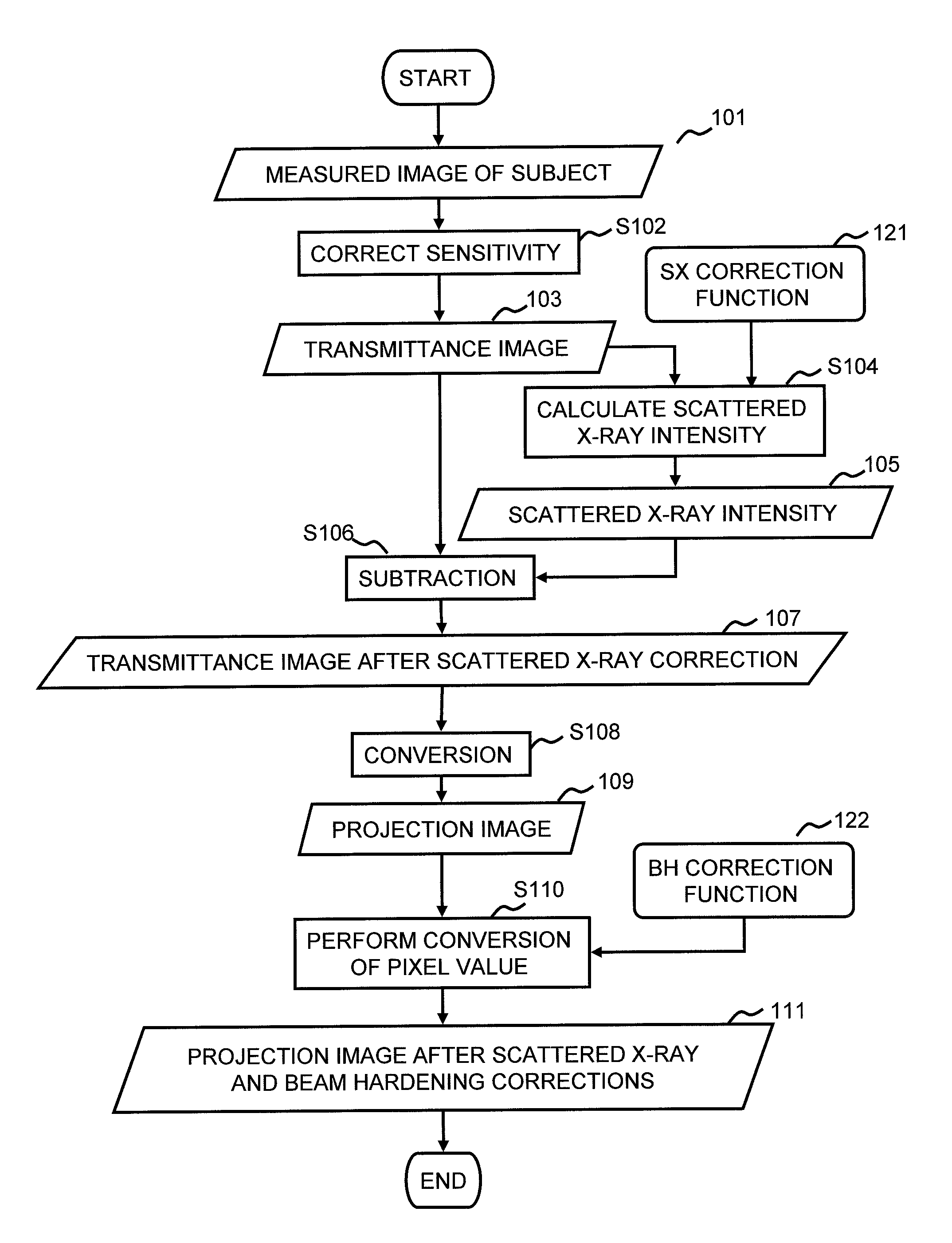
[0095]Next, a third embodiment to which the present invention is applied will be explained. The X-ray imaging apparatus of the present embodiment has basically the same configuration as each of the aforementioned embodiments. In each of the embodiments, the correction of scattered X-ray and the correction of influence caused by beam hardening are independently performed by using the SX correction function and the BH correction function, respectively. However, in the present embodiment, the correction for beam hardening is incorporated in the SX correction function. Accordingly, the correction of the measured data by using only the SX correction function achieves both the scattered X-ray correction and the beam hardening correction on the measured data after the scattered X-ray correction is performed. Hereinafter, with regard to the present embodiment, the SX correction function 123 that has a configuration different from each of the aforementioned embodiments and a correction proce...

second embodiment

[0101]It is to be noted that the correction process according to the present embodiment can be applied to the correction using the direct X-rays, in the same manner as the In other words, the correction value of the transmittance data D(ca, xj) calculated from the function D above is assumed as a value D′ (c0, xj), which is obtained according to the above procedure, by subjecting the transmittance data D(c0, xj) corresponding to the specific scattered X-ray amount calculated from the function D to the beam hardening correction. Then, the result is plotted on a graph showing the transmittance data D(ca, xj) in the real collimator width ca on the horizontal axis, and showing the transmittance data D′ (c0, xj) after the beam hardening correction is performed on the vertical axis, and then an approximate curve fitting the plotted result is assumed as the SX correction function 123′. It is to be noted that a linear equation, a quadratic equation, a polynominal equation, a logarithm func...


PUM


Abstract

Disclosed is an X-ray imaging apparatus in which a correction function used to correct scattered X-rays and a correction function used to correct beam hardening can be simply and precisely determined so that the correcting operations are performed in an appropriate sequence using the correction functions thus determined to enhance the precision in the correction and improve the image quality. The scattered X-rays and the beam hardening are corrected sequentially in this order, using the scattered X-ray correction function and the beam hardening correction function, both calculated using measured data for calculating the correction functions. The scattered X-ray correction function approximates as to each transmission distance, the data measured with changes in the transmission distance and with changes in the scattered X-ray amount, and associates the correction value thus obtained with transmittance data. Upon calculation of the beam hardening correction function, data measured with changes in the transmission distance is converted into projection data and is linearly approximated to obtain an ideal amount of beam hardening.

Description

TECHNICAL FIELD[0001]The present invention relates to a technique to enhance image quality in a radiation imaging apparatus. More particularly, the present invention relates to a technique for effectively correcting influences of scattered radiation and beam hardening.BACKGROUND ART[0002]A radiation imaging apparatus measures radiation (X-rays) passing through a subject, and obtains a static image or a moving image of the subject. On this occasion, scattered X-rays and beam hardening are considered as factors which reduce image contrast and precision of measured values and deteriorate image quality. The scattered X-rays, which are generated when X-rays pass through the subject, are mixed with direct X-rays being a net transmission amount, and incident on a detector which detects X-rays. The beam hardening, which occurs when X-rays passes through the subject and a part of energy is absorbed by the subject, causing variations in energy distribution, changes an X-ray absorption coeffic...

Claims


Application Information

Patent Timeline
Patent Type & Authority Patents(United States)
IPC IPC(8): A61B6/03G06T11/00
CPCG06T11/005A61B6/032A61B6/4441A61B6/4464A61B6/585G01T1/00
Inventor BABA, RIKA
Owner HITACHI LTD
Why Eureka
Try Eureka