Oil pump pressure control device

a technology of pressure control device and oil pump, which is applied in the direction of positive displacement liquid engine, separation process, liquid fuel engine, etc., can solve the problem of limiting the extent to which the sub-pump flow rate (pressure) is caused to fluctuate by the valve alone, increasing the pipe load and generated noise, etc. problem, to achieve the effect of reducing the pressure of the second rotor assembly, reducing the amount of unnecessary work, and dimensional precision

Inactive Publication Date: 2011-10-18
YAMADA MANUFACTURING CO LTD
View PDF11 Cites 90 Cited by
  • Summary
  • Abstract
  • Description
  • Claims
  • Application Information

AI Technical Summary

Benefits of technology

[0011]The effect of the invention as claimed in claim 1 is to prevent a drop in the overall pump pressure at times of high-speed revolution when the second discharge passage of the second rotor assembly is fully closed so as to form the second rotor assembly as an independent circuit whereupon, even in the absence of a superfluous work pressure being generated by the second rotor assembly, there is no drop in overall pump pressure. In addition, because work=pressure×flow rate the superfluous work can be reduced if the pressure is lowered. As described in the conventional art, when the first discharge passage of the first rotor assembly and the second discharge passage of the second rotor assembly are in communication, the pressure of the second rotor assembly does not drop below the pressure of the return passage of the first rotor assembly. In addition, because the second rotor assembly is formed as an independent circuit during high-speed revolution, provided the opened area of the return passage of the second rotor assembly is enlarged, more oil can be discharged and the pressure of the second rotor assembly further decreased. In addition, in the second rotor assembly, because the second discharge passage of the second rotor assembly is fully closed at times of high revolution, the flow rate (pressure) of the pump as a whole is influenced by the flow rate (pressure) of the first rotor assembly only.
[0012]In addition, because the exhibited appearance of the flow rate of the second rotor assembly (pressure) at times of high-speed revolution is removed, the influence thereof on pump as a whole is removed and, accordingly, the pump characteristics shift from a stepped characteristic to a linear characteristic, and the need for further significant alteration to the dimensional precision, which has been an inherent problem in conventional variable flow rate pumps, is eliminated. Because the first rotor assembly and the second rotor assembly constitute separate discharge sources and comprise separate discharge passages to the valve, the control of the two circuits performed by the valve can be more precisely executed (there are limits to the valve control when communication occurs prior to the valve). In addition, because the second discharge passage of the second rotor assembly does not extend downstream of the valve, the second rotor assembly is more liable to be affected by the valve opening / closing, and alteration to the flow rate (pressure) of the second rotor assembly by means of the valve is easy. In addition, because there are two discharge sources, the amount of work performed by a single rotor can be reduced, and superfluous work further reduced.
[0013]In the invention of claim 2 in which the aforementioned first rotor assembly and the aforementioned second rotor assembly are configured as separate oil pumps, vibration, noise and discharge pulse and so on are able to be negated and reduced by the two pumps. Furthermore, in the invention of claim 3 in which the aforementioned first rotor assembly and the aforementioned second rotor assembly are configured as a single oil pump having at least three rotors, a reduction in the space, weight, and number of component parts can be achieved.

Problems solved by technology

However, relief occurs even at times of high-speed revolution while the sub pump and main pump in communication and, accordingly, gives rise to the following problems.
While a valve is regulated in order to reduce superfluous work, fluctuations in the main flow rate and the sub flow rate (pressure) created by regulation of the valve relief position are directly linked to all fluctuations in overall flow rate (pressure) of the pump, a large number of steep inflection points caused by displacement and resultant overlapping of inflection points of the main flow rate and the sub flow rates occur in the overall flow rate (pressure) of the pump, vibration is generated by this large number of steep points and, accordingly, the pipe load and generated noise increases.
In addition, because the discharge oil passage of the sub-pump passes through the valve and is subsequently immediately coupled to the main pump, there is a limit to the extent to which the sub pump flow rate (pressure) is caused to fluctuate by the valve alone.

Method used


Image

  • Oil pump pressure control device
  • Oil pump pressure control device
  • Oil pump pressure control device

Examples


first embodiment

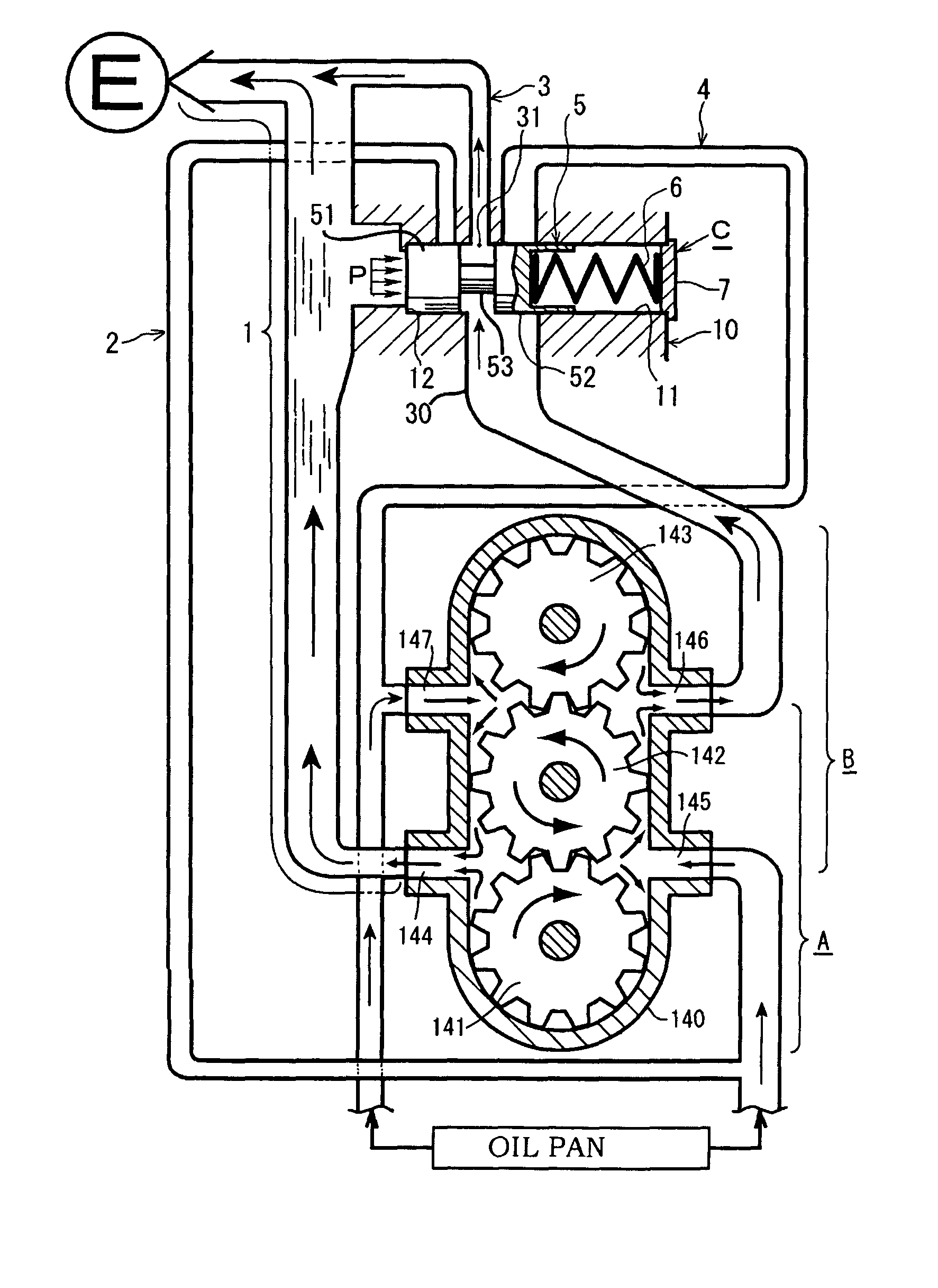
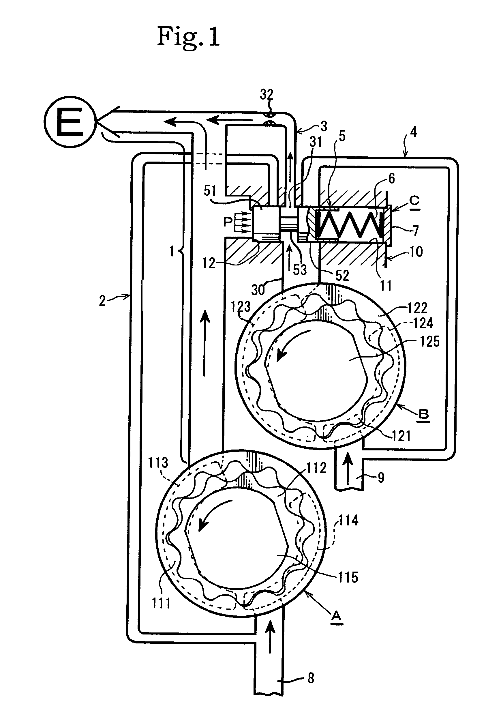
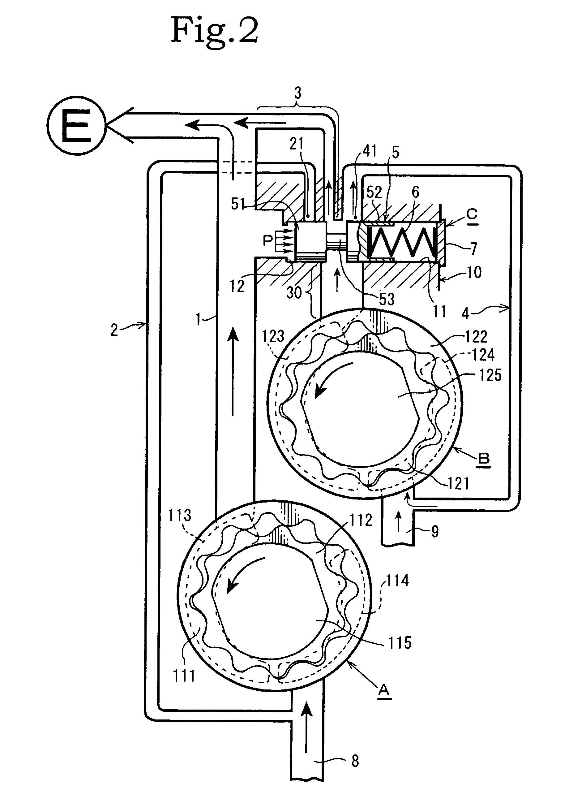
[0023]In a description of the embodiments of the present invention given hereinafter with reference to the drawings, as shown in FIG. 1 to FIG. 3, the symbol A denotes a first rotor assembly and B denotes a second rotor assembly, each of which constitutes an oil pump configured from an outer rotor, an inner rotor and discharge port, and an intake port and so on provided in a casing. The device is configured from a first discharge passage 1 for feeding oil to an engine E, a first return passage 2 that returns to an intake passage 8 of the aforementioned first rotor assembly A, a second discharge passage 3 for feeding oil to the engine E, and a second return passage 4 that returns to an intake passage 9 of the aforementioned second rotor assembly B, an end portion side of the aforementioned second discharge passage 3 being coupled with the aforementioned first discharge passage 1 at a suitable position therealong. The first rotor assembly A and second rotor assembly B of this first em...

third embodiment

[0037]The operation of the pressure control valve C of the first rotor assembly A and second rotor assembly B of the third embodiment will be hereinafter described. First, in the low revolution range of the first rotor assembly A and second rotor assembly B, in other words, when the engine revolution number is in the low revolution range which constitutes the state of FIG. 7, the operation of the first valve portion 51 and second valve portion 52 of the pressure control valve C is the same as that of FIG. 1 and, accordingly, a description thereof has been omitted. The characteristics in the low revolution range under these conditions are shown in the characteristics graph of the revolution number and discharge pressure [see FIG. 5A] or characteristics graph of revolution number and discharge flow rate [see FIG. 5B].

[0038]A state in which the engine revolution number has risen further is taken as the intermediate revolution range. In this state, which constitutes the state of FIG. 8,...


PUM

PropertyMeasurementUnit
area flow rateaaaaaaaaaa
frictionaaaaaaaaaa
pressureaaaaaaaaaa

Abstract

A device including a first discharge passage from a first rotor assembly to an engine, a first return passage that returns to an intake side of the first rotor assembly, a second discharge passage from a second rotor assembly to the engine, a second return passage that returns to an intake side of the second rotor assembly, and a pressure control valve whose valve main body is provided between a discharge port from the second rotor assembly and the first discharge passage. The first discharge passage and the second discharge passage are coupled, and a flow passage control is executed in each of: a low revolution range; an intermediate revolution range; and a high revolution range.

Description

BACKGROUND OF THE INVENTION[0001]1. Field of the Invention[0002]The present invention relates to an oil pump pressure control device that facilitates a reduction in friction while maintaining characteristics identical to the pressure characteristics of a common oil pump based on the provision of a plurality of discharge sources and a newly devised method of switching oil passages.[0003]2. Description of the Related Art[0004]While a variable flow rate oil pump of the conventional art comprises two discharge ports configured from a single discharge port partitioned into two, because of the single rotor assembly thereof, from the viewpoint of the discharge source there is still a single discharge port. In addition, at times of high revolution when the amount of power consumed by the pump is high, oil passages of a main pump (first pump) and a sub-pump (second pump) are in communication. Accordingly, the pressure of the main pump is substantially equivalent to the pressure of the sub-pu...

Claims


Application Information

Patent Timeline
Patent Type & Authority Patents(United States)
IPC IPC(8): F04B49/00
CPCF04C14/26F04C14/065F04C2/10F04C2/18Y10T137/86019
Inventor ONO, YASUNORIKAI, KEIICHIFUJIKI, KENICHIYAMANE, KOSUKE
Owner YAMADA MANUFACTURING CO LTD
Why Eureka
Try Eureka