
Power tool adapter for remotely actuating a power tool mounted on an end of a hot stick using an insulating pull-rope

a technology of power tools and pull-ropes, which is applied in the direction of power tools, manipulators, overhead lines/cables, etc., can solve the problems of many overuse injuries, physical demands of manual manipulating hot sticks, and a great effort to reposition the socket onto the nut, so as to reduce the incidence of overuse injuries

Active Publication Date: 2018-05-10
JEREMENKO JASON A
View PDF4 Cites 10 Cited by
  • Summary
  • Abstract
  • Description
  • Claims
  • Application Information

AI Technical Summary

Benefits of technology

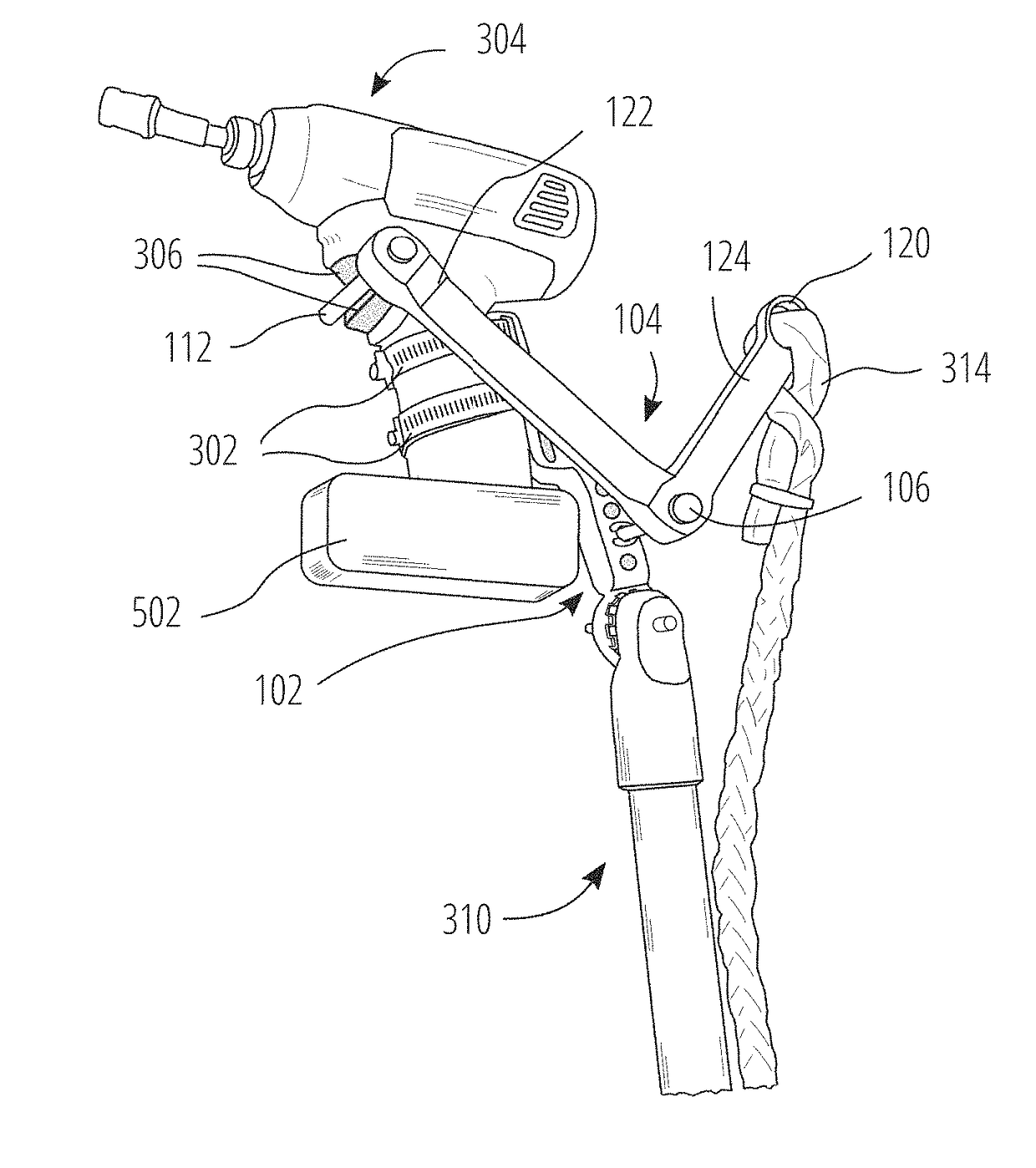
The remote adapter of this invention allows a lineman to easily mount different power tools on the end of their hot stick, reducing the risk of injury and improving efficiency. The use of power tools at the end of a hot stick also increases productivity and allows for faster and easier tightening of bolts and nuts. The remote adapter is designed to be easily activated with a pull-rope, making it simple for electrical linemen to use. Its dimensions are optimized to provide leverage and minimize the force required for pull-rope pulling. The pull member is 4.25 inches long, and the trigger member, which moves to activate the power tool trigger, is 6 inches long.

Problems solved by technology

Since the hot stick can be many feet long, (e.g., 3 feet to 30 feet), manually manipulating the hot stick can be physically demanding.
Often, during this process, the socket slips off of the nut or bolt, and it requires a great effort to reposition the socket onto the nut or bolt to begin the tightening or loosening motion again.
During this strenuous exercise, a lineman's shoulders, hands, forearms, and back are continually exerted, and as a result, many overuse injuries have occurred.
However, these devices are not suitable for use in a high voltage environment.

Method used


Image

  • Power tool adapter for remotely actuating a power tool mounted on an end of a hot stick using an insulating pull-rope
  • Power tool adapter for remotely actuating a power tool mounted on an end of a hot stick using an insulating pull-rope
  • Power tool adapter for remotely actuating a power tool mounted on an end of a hot stick using an insulating pull-rope

Examples


Embodiment Construction

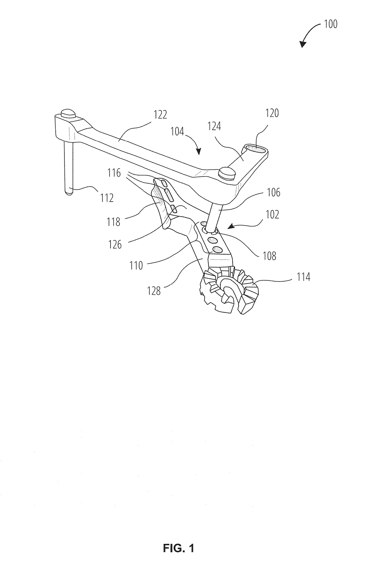
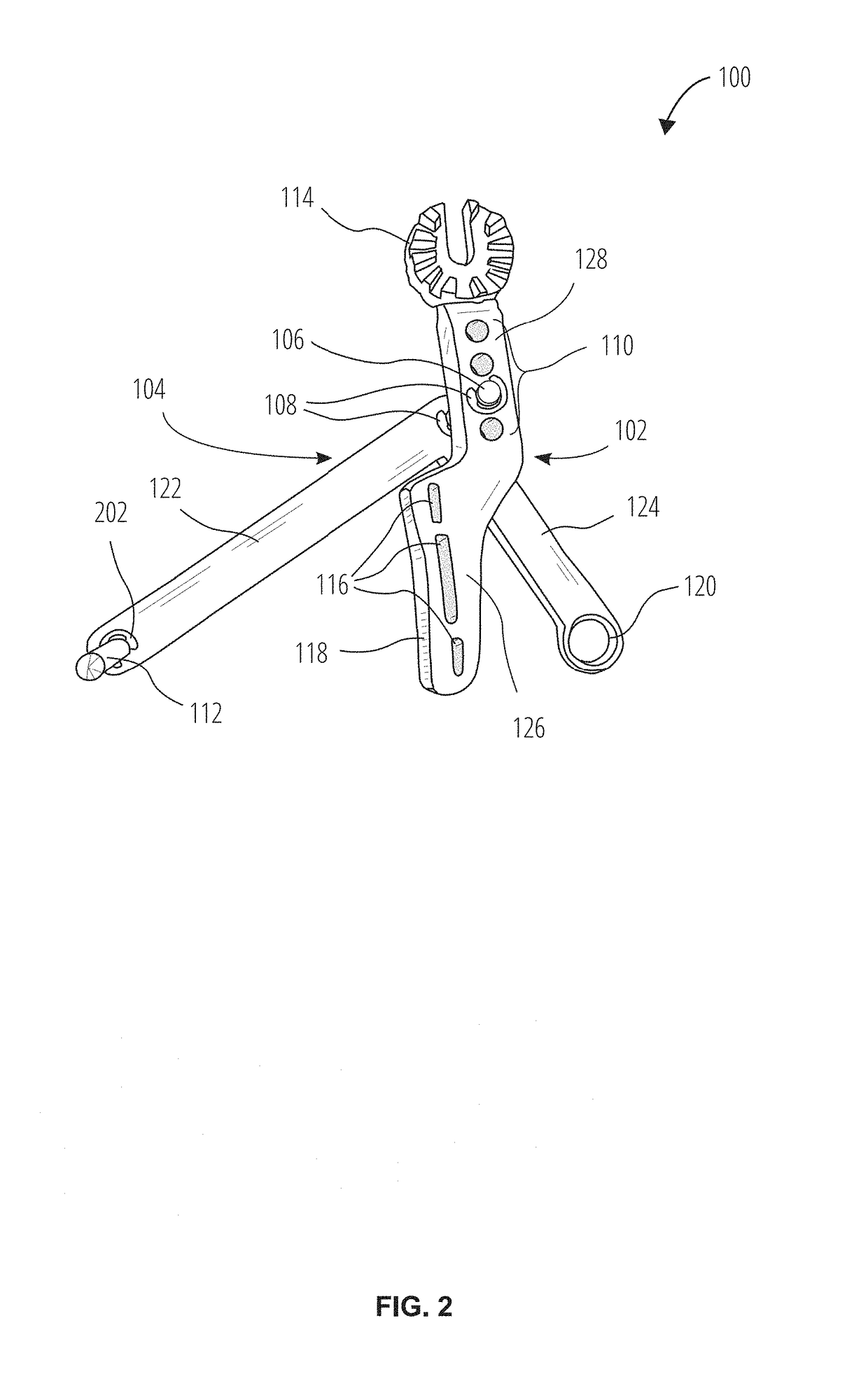
[0036]FIG. 1 shows an embodiment of a remote adapter 100 having a body 102 and an actuator lever arm 104 attached to the body 102 with a pivot pin 106 that allows the actuator lever arm 104 to pivot with respect to the body 102.

[0037]In this embodiment, a hole portion 128 of the body 102 has four body pivot holes 110, one of which receives the pivot pin 106. There are four body pivot holes 110 to accommodate adjustment of the position of the actuator lever arm 104. Adjusting the position of the actuator lever arm 104 will adjust the position of a trigger pin 112, which is inserted into a trigger member 122 of the actuator lever arm 104.

[0038]In this embodiment, the pivot pin 106 is secured to the body 102 using a pivot pin clip ring 108 on the inside surface of the body 102, and on the opposite side of the body 102 another pin clip ring (not shown) is also used to secure the pivot pin 106 to the body 102.

[0039]The actuator lever arm 104 has a pull member 124 with a rope attachment f...


PUM


Abstract

A remote adapter for use with a lineman's hot stick that enables the lineman to mount a wide variety of power tools onto the far end of the hot stick for tasks involving high voltage equipment. The remote adapter allows the power tool to be actuated by pulling on an insulating pull-rope. The remote adapter includes a body for supporting the power tool, the body including: at least one slot for receiving at least one strap configured to strap the power tool to the body, at least one pivot hole for receiving a pivot pin, and a splined universal connector for attachment to a hot stick. The remote adapter also includes a lever arm that is pivotable with respect to the body. The lever arm includes a hole for receiving a trigger pin which actuates the power tool trigger when the insulating rope attached to an attachment feature is pulled.

Description

CROSS-REFERENCE TO RELATED APPLICATIONS[0001]This application claims the priority of U.S. Provisional Application No. 62 / 417,900, filed Nov. 4, 2016, the entire contents of which is herein incorporated by reference.FIELD OF THE INVENTION[0002]This invention relates generally to power tools, and more particularly to apparatus for remotely supporting and actuating a power tool.BACKGROUND OF THE INVENTION[0003]Electrical linemen perform installation and maintenance work on high voltage power lines. As a routine part of their work, linemen require tools, such as tools to tighten and loosen nuts and bolts that are electrified at high voltages.[0004]To prevent electrical shock and injury, linemen often use insulating equipment. For example, a lineman's hot stick is a non-conducting pole made from an insulating material, such as fiberglass. A hot stick includes a splined universal head at the far end of the hot stick. The splined universal head is commonly used for mounting tools to the fa...

Claims


Application Information

Patent Timeline
Patent Type & Authority Applications(United States)
IPC IPC(8): B25H1/00B25F5/02H02G1/02
CPCB25H1/0035B25F5/02H02G1/02B25B21/00B25J1/04
Inventor JEREMENKO, JASON A.
Owner JEREMENKO JASON A
Learn More