Flexible riser pipe installation for conveying hydrocarbons

Active Publication Date: 2014-05-27
TECH FRANCE SA
View PDF20 Cites 13 Cited by
  • Summary
  • Abstract
  • Description
  • Claims
  • Application Information

AI Technical Summary

Benefits of technology

[0028]The present invention advantageously applies to any flexible pipe of the unbonded type provided that it comprises at least one internal sealing sheath and one pair of tensile armor wires.
[0029]Advantageously, the buoy is engineered to apply to the riser a tension T greater than at least 75% of the maximum reverse end-cap effect F developed at the foot of the riser, and more advantageously still, the buoy is engineered to apply to the riser a tension T greater than at least 100% of the maxium reverse end-cap effect F developed at the foot of the riser. In the latter instance, it is possible to ensure that the tensile armor will never be placed in compression by the reverse end cap effect and it is therefore particularly advantageous to choose to produce the flexible pipe using tensile armor wires based on carbon fiber. Such tensile armor layers offer the advantage of lightne

Problems solved by technology

In addition, the flexible pipe is also subjected to dynamic bending stresses, particularly when it is being installed or when it is in service in the case of a riser, that is to say a pipe that makes the connection between a service installation at sea level or thereabouts, and an installation at the bottom of the sea.
All of these stresses may cause the wires of the tensile armor layer to buckle and may irreversibly disorganize the tensile armor layers, thus destroying the flexible pipe.
However, while this solution does solve the problems associated with the radial buckling of the wires that make up the tensile armor layers, it is capable only of limiting the risk of lateral buckling of said wires, which still remains.
However, while this solution reduces the risk of lateral buckling of the tensile armor layers, it does not completely eliminate it.
These solutions are effective but have a certain number of constraints, particularly financial ones, which have led to a desire for alternative solutions, at least for specific cases, particularly for the specific case of risers.
This configuration has the advantage of simplicity but the disadvantage of being ill-suited to dynamic applications at small depths because of the excessive variations in curvature that may be generated near the seabed.
However, this configuration is commonly used for very deep applications, that is to say applications at depths in excess of 1000 m, or even 1500 m. This is because under such conditions, the relative amplitude of the movements of the floating support, particularly the vertical movements associated with the swell, remains very much smaller than the length of the catenary, thus limiting the amplit

Method used


Image

  • Flexible riser pipe installation for conveying hydrocarbons
  • Flexible riser pipe installation for conveying hydrocarbons
  • Flexible riser pipe installation for conveying hydrocarbons

Examples


first embodiment

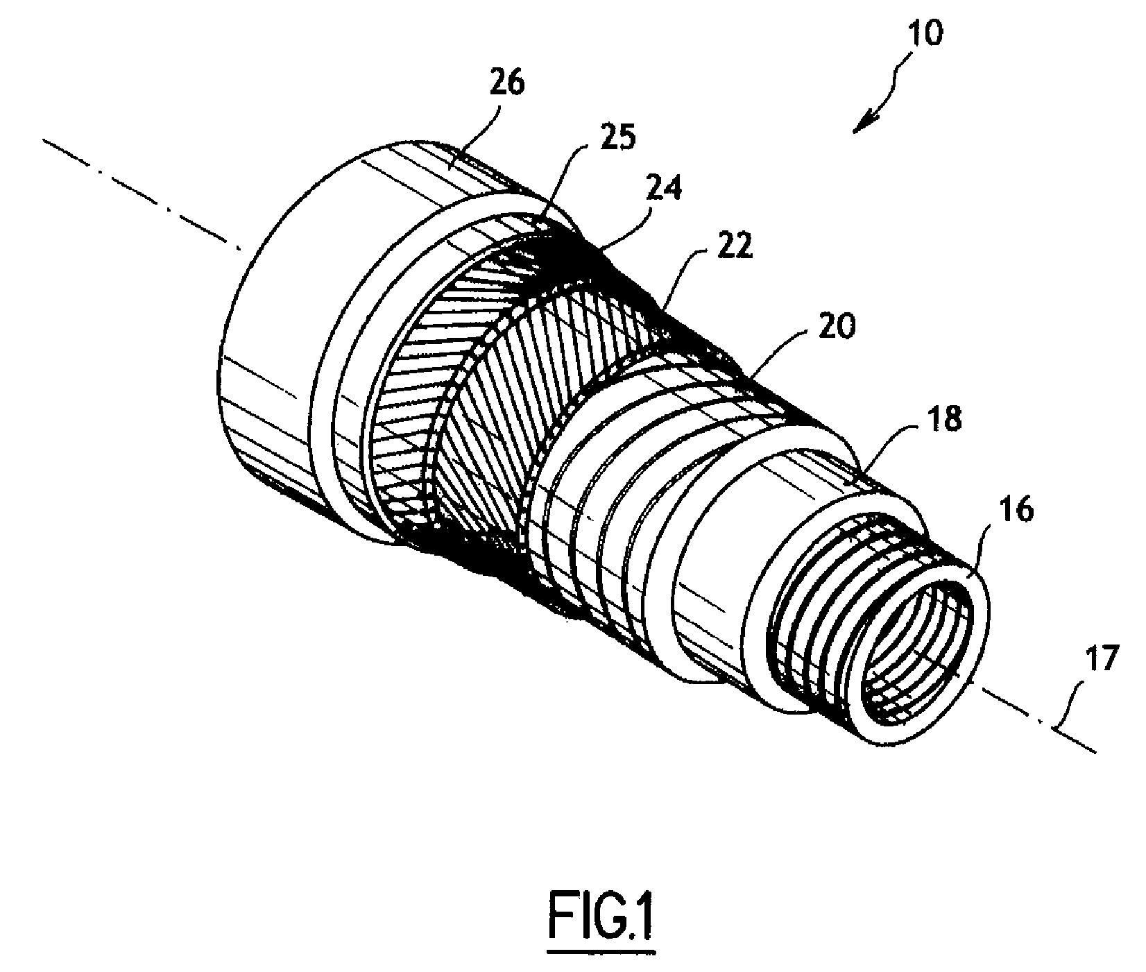
[0077]According to the invention, the tension T at the foot of the riser is equal to 50% of F, that is to say to 88 000 daN. The flexible pipe 10 in this case has to be engineered to withstand an axial compressive force of the order of 90 000 daN rather than the aforementioned 180 000 daN according to the prior art. This substantial reduction in axial compression makes it possible in this example to choose a structure comprising two tensile armor layers 22, 24 made of steel each 3 mm thick and made up of conventional wires that do not have a high width-to-thickness ratio. The thickness of the anti-expansion Kevlar® layer 25 in this instance is practically half that according to the aforementioned prior art. The in-water weight of such a pipe, when full of gas, is of the order of 90 daN per linear meter, that is to say appreciably lower than that of a pipe according to the aforementioned prior art. The total in-water weight of the pipe 10 is therefore around 162 000 daN. As a result,...

second embodiment

[0079]According to a particularly advantageous second embodiment of the invention, the tension T at the foot of the riser is equal to F, that is to say to 176 000 daN.

[0080]In this case, insofar as the reverse end cap effect F is completely compensated for and insofar as it is possible to avoid placing the tensile armor layers 22, 24 in compression, it is possible and advantageous to choose for these tensile armor layers wires made of a composite material, preferably based on carbon fiber. Reference may, for example, be made to document U.S. Pat. No. 6,620,471 in the name of the Assignee Company, which discloses composite tapes comprising composite fibers embedded in a thermoplastic matrix. Such reinforcing armor affords good tensile strength and leads to a lighter weight flexible pipe than metal armor. By contrast, as they have poor compressive strength, they can be used only under conditions in which the risk of being placed in compression is averted, which it is with the inventio...


PUM


Abstract

The invention relates to a riser pipe installation that comprises a flexible duct of the non-bound type, the duct being vertically arranged between a mechanical connection with a submerged buoy at the stub on the one hand, and a mechanical connection with the seabed at the bottom on the other hand, wherein fluid connections are provided at the stub and at the bottom for connecting the riser pipe with surface equipment on the one hand and bottom equipment on the other hand; the bottom of the pipe is located at a depth of at least 1000 m where it is submitted to a computable maximum reverse bottom effect F, while the buoy is oversized in order to generate at the bottom of the riser pipe a reaction tension T higher than at least 50% or even 100% of the computable maximum reverse bottom effect F applied at the bottom of the pipe.

Description

CROSS REFERENCE TO RELATED APPLICATION[0001]The present application is a 35 U.S.C. §§371 national phase conversion of PCT / FR2008 / 000079, filed Jan. 23, 2008, which claims priority of French Application No. 0700549, filed Jan. 26, 2007, the disclosure of which is incorporated by reference herein. The PCT International Application was published in the French language.BACKGROUND OF THE INVENTION[0002]The present invention relates to a flexible riser installation for conveying hydrocarbons or other fluids under pressure and to a method of creating such an installation.[0003]Flexible pipes for conveying hydrocarbons, as opposed to rigid pipes, are already well known and generally comprise, from the inside of the pipe outward, a metal carcass, to react the radial crushing forces, covered by an internal sealing sheath made of polymer, a pressure vault to withstand the internal pressure of the hydrocarbon, tensile armor layers to react axial tensile forces and a polymer external sheath to p...

Claims


Application Information

Patent Timeline
IPC IPC(8): F16L1/12E21B43/013
CPCE21B43/013E21B17/012E21B17/015
Inventor ESPINASSE, PHILIPPECOUTAREL, ALAINWACLAWEK, ISABEL TERESA
Owner TECH FRANCE SA
Why Eureka
Try Eureka