Methods and apparatus for creating turbulence in a thermostatic mixing valve

a thermostatic mixing valve and thermostatic technology, applied in the direction of temperatue control, process and machine control, instruments, etc., can solve problems such as difficulty in achieving

Active Publication Date: 2016-11-29
MAGARL
View PDF100 Cites 7 Cited by
  • Summary
  • Abstract
  • Description
  • Claims
  • Application Information

AI Technical Summary

Problems solved by technology

However, hot and cold fluid have a tendency to remain separate unless mixing is induced within the valve assembly, which can be difficult to achieve in the relatively small amount of space available for mixing within a typical valve assembly.

Method used


Image

  • Methods and apparatus for creating turbulence in a thermostatic mixing valve
  • Methods and apparatus for creating turbulence in a thermostatic mixing valve
  • Methods and apparatus for creating turbulence in a thermostatic mixing valve

Examples


Embodiment Construction

[0037]For the purposes of promoting an understanding of the principles of the invention, reference will now be made to the embodiments illustrated in the drawings and specific language will be used to describe the same. It will nevertheless be understood that no limitation of the scope of the invention is thereby intended, such alterations and further modifications in the illustrated device, and such further applications of the principles of the invention as illustrated therein being contemplated as would normally occur to one skilled in the art to which the invention relates. At least one embodiment of the present invention will be described and shown, and this application may show and / or describe other embodiments of the present invention. It is understood that any reference to “the invention” is a reference to an embodiment of a family of inventions, with no single embodiment including an apparatus, process, or composition that should be included in all embodiments, unless otherw...


PUM


Abstract

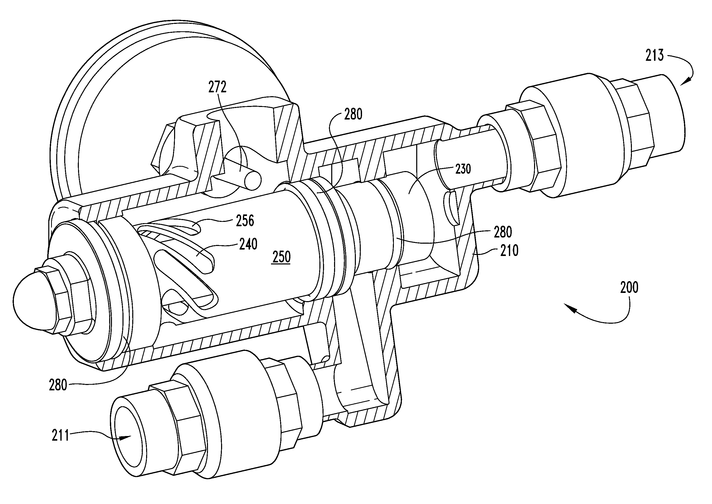
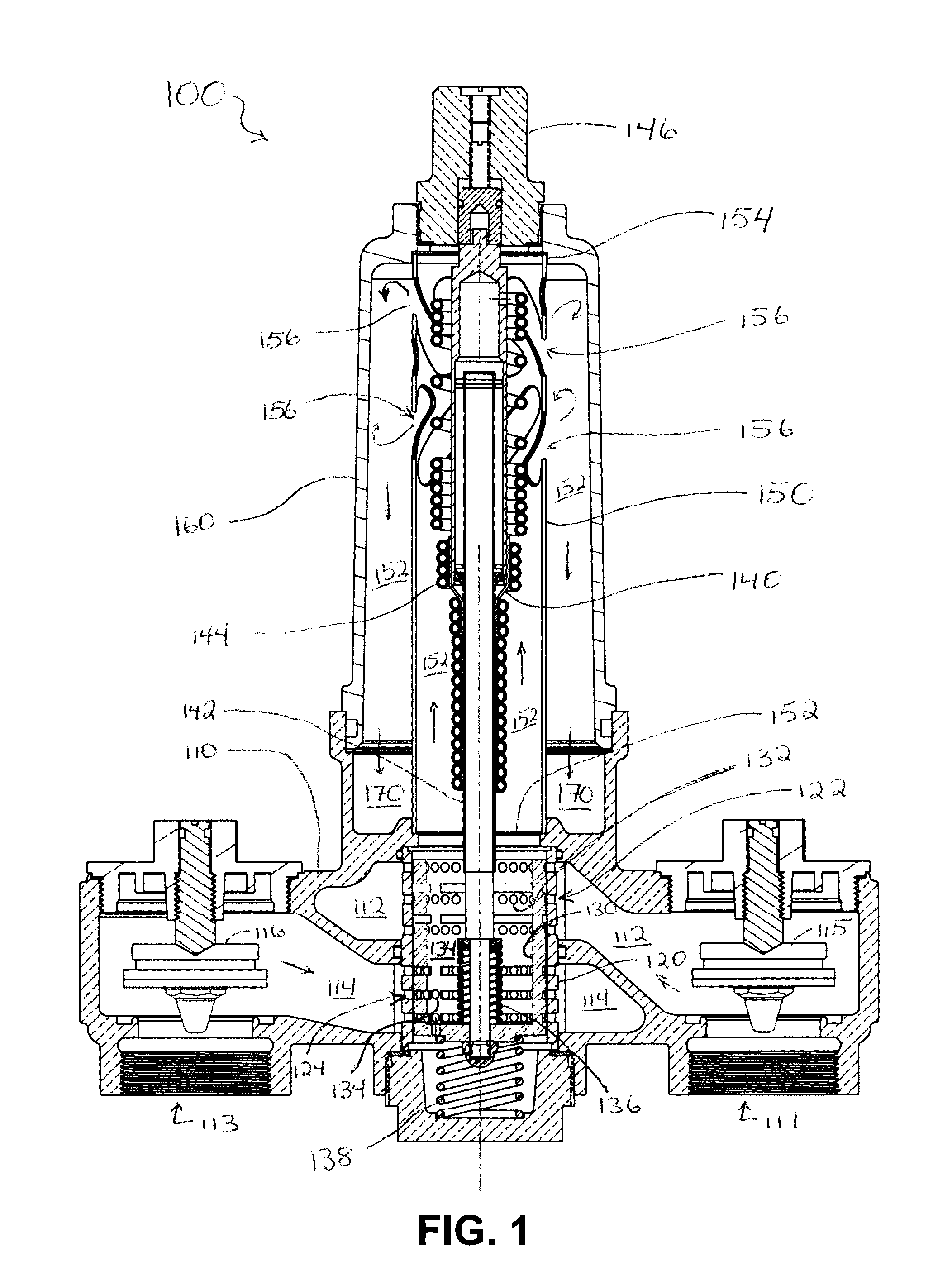
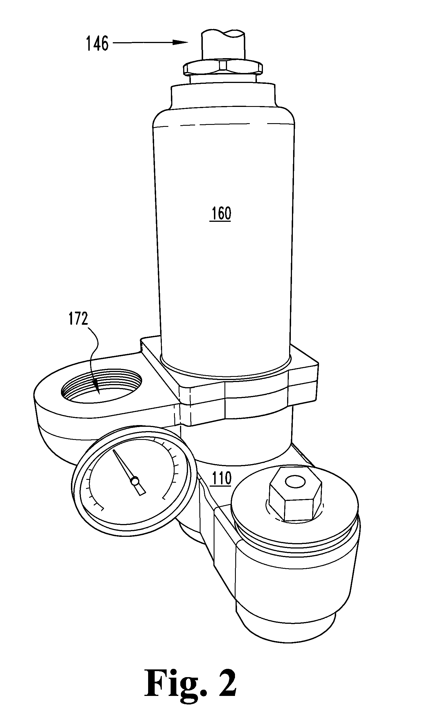
Mixing valve turbulence generators and methods are disclosed. Embodiments include turbulence generation apparatuses and methods that increase the turbulence of, impart swirl to, reverse the direction of, create tortuous paths for, and / or accelerate the mixing of hot and cold fluid within a valve assembly. Alternate embodiments include angled radial slots, angled surfaces and fin-like baffles to enhance the mixing of hot and cold fluids.

Description

CROSS REFERENCE TO RELATED APPLICATION[0001]This application claims the benefit of priority to U.S. Provisional Patent Application Ser. No. 61 / 550,396, filed Oct. 22, 2011, entitled MIXING VALVE TURBULENCE GENERATORS AND METHODS, incorporated herein by reference.FIELD OF THE INVENTION[0002]Various embodiments the present invention pertain to improvements in the mixing of multiple fluid streams within a body, and in particular to the mixing of hot and cold fluid streams in a thermostatically controlled valve.BACKGROUND OF THE INVENTION[0003]Mixing valves are generally used to mix a warmer fluid (hereinafter referred to as the “hot” fluid) with a cooler temperature fluid (hereinafter referred to as the “cold” fluid) to deliver a fluid at a desired temperature. Frequently the fluid being mixed is water. The fluid exiting the mixing valve is frequently at a temperature between the hot fluid and the cold fluid. However, the valve may also deliver fluid at a temperature equal to either th...

Claims


Application Information

Patent Timeline
Patent Type & Authority Patents(United States)
IPC IPC(8): G05D23/13B01F5/00
CPCB01F5/008G05D23/1346B01F25/1051
Inventor BAKER, THOMAS R.
Owner MAGARL
Why Eureka
Try Eureka