
Hydraulically controlled thermostatic mixing valve

a thermostatic mixing and thermostatic technology, applied in the direction of temperature control with auxiliaries non-electric power, process and machine control, instruments, etc., can solve the problems of sudden increase in the temperature of the shower water, significant discomfort or injury to the user, and potentially dangerous situations, and achieve the effect of stable liquid outflow temperatur

Inactive Publication Date: 2010-11-16
RIVLIN EITAN
View PDF34 Cites 5 Cited by
  • Summary
  • Abstract
  • Description
  • Claims
  • Application Information

AI Technical Summary

Benefits of technology

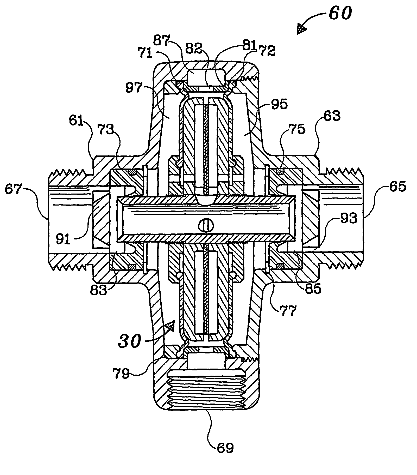
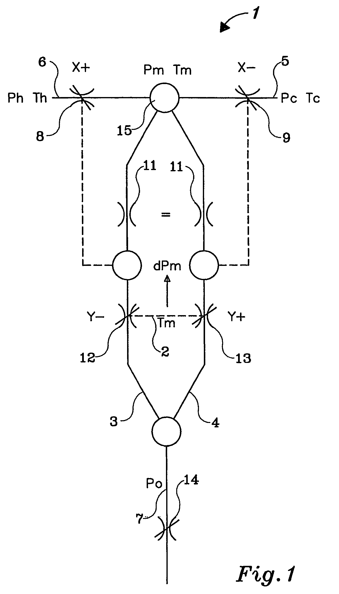
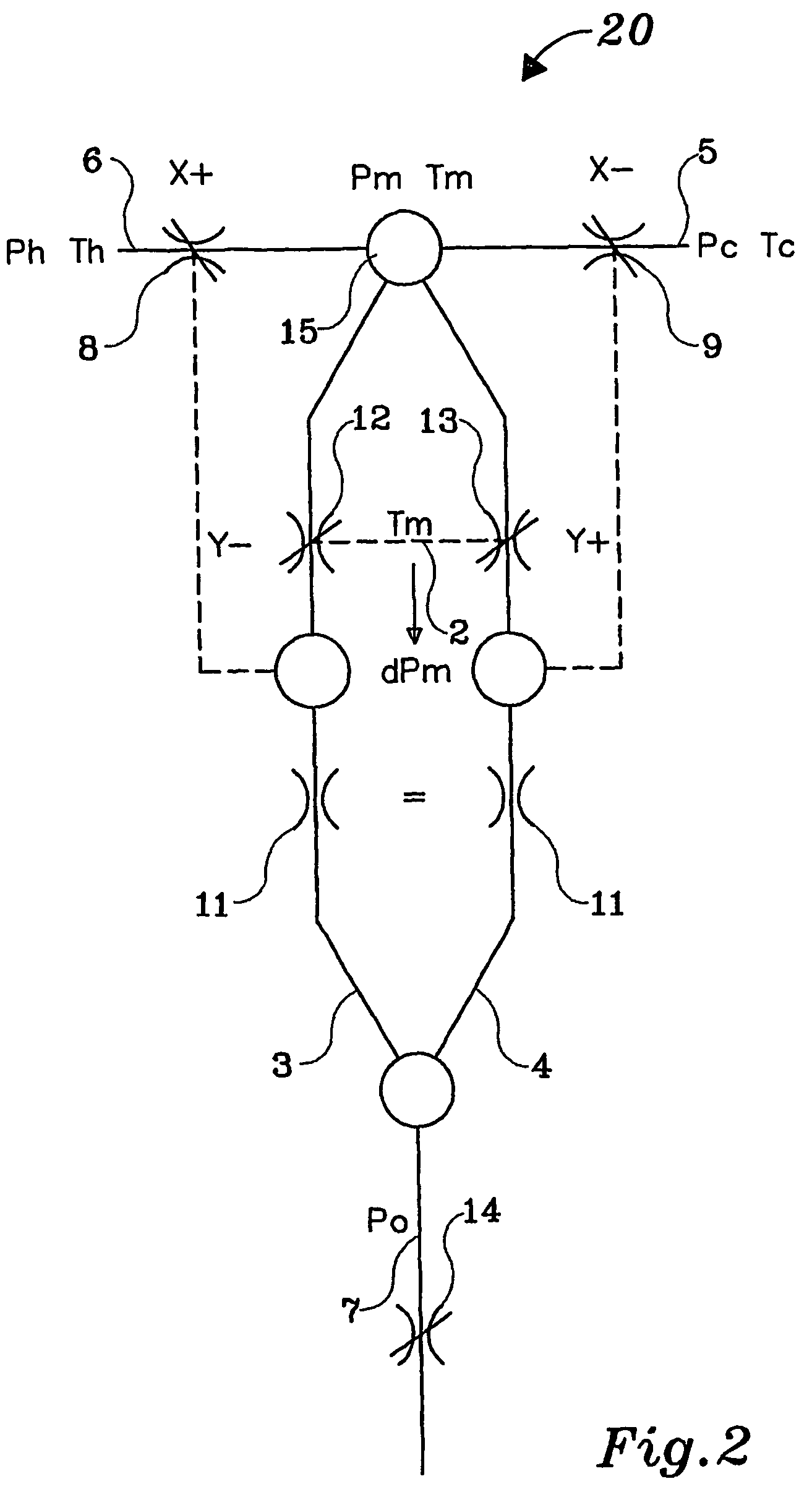
"The present invention provides a hydraulic control mechanism for a mixing valve that is simple and compact. The absence of a mechanical link between the control element and the housing results in a stable liquid outflow temperature even if there is a variation in the hot and cold supply. The valve is designed to protect against failure due to solid particles and does not require an electrical power supply. The mixing regulation assembly is operative in response to a difference in temperature or pressure between the two fluid streams and includes a housing with a temperature adjusting mechanism. The mixing regulation assembly includes a mixing element, a stream divider, and a flow controlling mechanism. The invention also provides a mixing valve that is stable and reliable, even in situations where there is a variation in the temperature or pressure of the fluid streams."

Problems solved by technology

In extreme cases, the resulting change in temperature of the water from an outlet can result in substantial discomfort or injury to the user, most especially in a shower cubicle.
A sudden pressure drop in the cold water supply, such as occurs when an adjacent toilet is flushed, will result in a sudden increase in the temperature of the shower water and a potentially dangerous situation.
This type of valve, however, will not respond to a decrease in the temperature of water in the hot water supply line.
It will therefore not compensate for a gradual temperature change that occurs as the hot water tank cools off due to peak household demand or as the household demand is subsequently reduced.
The design of such pressure equalizing valves is complex and these are still affected by any temperature changes of the incoming fluids.
Consequently, these pressure equalizing valves cannot maintain a stable temperature.
However, such directly driven thermostatically controlled valves fail to provide a constant outlet water temperature but, instead, greatly reduce the deviation of the outlet water temperature from a preselected temperature consequent to temperature or pressure changes in the supply lines.
As the proportioning valve responds the outlet water temperature changes and eventually causes the temperature responsive mechanism to reverse the direction of its movement, giving rise to a period of oscillations.
It should be noted that most servomechanism valves do not respond in the theoretical fashion described above given a hot and cold inlet water extreme pressure imbalance because the imbalance alters the equilibrium position of the valve member.
Furthermore, the disclosed servomechanism valves are extremely large compared to conventional valves.
Also, common to servomechanism valves and two stage valve assemblies, the long narrow fluid passageways are easily clogged by suspended particles in the water supply.
The major disadvantage of this valve is a substantial increase in the number of components, the cost of assembly, and the space required for the valve assembly compared to one-stage valves.
These devices are expensive and not applicable, for example, to a domestic shower.
There is a significant drawback to this mixing valve.
This operative flow is carried in a small-bore conduit, as a result of which there is a substantial risk of blockage of the small-bore conduit.

Method used


Image

  • Hydraulically controlled thermostatic mixing valve
  • Hydraulically controlled thermostatic mixing valve
  • Hydraulically controlled thermostatic mixing valve

Examples


Embodiment Construction

[0095]The present invention seeks to provide a solution to the problem of providing a constant, stable temperature from separate supplies of hot and cold water or other fluids in various environments, including but not limited to industry, hospitals, sports clubs, hotels and homes, including end point uses such as basins and showers. While this is not an insuperable problem, a successful solution must provide a device, which is simple to install, requires no electrical power for reasons of safety, is compact, and protects the user from the danger of exposure to scalding hot water or the discomfort of cold water. Furthermore, the output temperature must remain stable at a pre-selected level in spite of fluctuations in both temperature and pressure of either of the supplies of hot and cold water consequent to load changes in the supply lines. The most problematic scenario to be avoided relates to a substantially total supply failure of cold water, potentially exposing the user to esse...


PUM


Abstract

A fluid mixing valve for producing a mixed fluid stream from first and second inlet fluid streams having different, varying temperatures, and having different, varying pressures, the mixed fluid stream having a substantially stable, preselected temperature of a magnitude between the temperatures of the first and second inlet fluid streams, the fluid mixing valve including a housing and a mixing regulation assembly disposed within the housing. The invention also provides a method for producing a mixed fluid stream from first and second inlet fluid streams having different, varying temperatures, and having different, varying pressures, the mixed fluid stream having a substantially stable, preselected temperature of a magnitude between the temperatures of the first and second fluid streams.

Description

FIELD OF THE INVENTION[0001]The present invention relates to thermostatic mixing valves and, more specifically, to hydraulic control of thermostatic mixing valves.BACKGROUND OF THE INVENTION[0002]It is known in the art to provide a thermostatic mixing valve to control the temperature of warm water by controlling the proportions of supplied hot and cold water.[0003]From the time that piped hot and cold running water became a common feature of architecture there has been an awareness of the occasional inconvenience resulting from a sudden change in temperature or pressure to the hot or cold water supplied to a common outlet such as a shower. In extreme cases, the resulting change in temperature of the water from an outlet can result in substantial discomfort or injury to the user, most especially in a shower cubicle. A sudden pressure drop in the cold water supply, such as occurs when an adjacent toilet is flushed, will result in a sudden increase in the temperature of the shower wate...

Claims


Application Information

Patent Timeline
Patent Type & Authority Patents(United States)
IPC IPC(8): G05D23/12G05D23/02G05D23/13
CPCG05D23/1313
Inventor RIVLIN, EITAN
Owner RIVLIN EITAN
Learn More