Lockable switch mechanism

a switch mechanism and lockable technology, applied in the direction of electric switches, air-break switches, electrical appliances, etc., can solve the problems of relative bulky and complex

Inactive Publication Date: 2005-03-29
ROCKWELL AUTOMATION
View PDF10 Cites 37 Cited by
  • Summary
  • Abstract
  • Description
  • Claims
  • Application Information

AI Technical Summary

Benefits of technology

According to the present invention, there is provided a lockable switch mechanism comprising a switch plunger which is mounted in a housing and is displaceable relative to the housing along a predetermined axis between a first unlocked position and a second position, a locking mechanism for locking the switch plunger in the second position, and a switch mechanism which is actuated by movements of the switch plunger between the first and second positions, wherein the locking mechanism comprises at least one first locking member which is biased against a surface o...

Problems solved by technology

This arrangement works well b...

Method used


Image

  • Lockable switch mechanism
  • Lockable switch mechanism
  • Lockable switch mechanism

Examples


Embodiment Construction

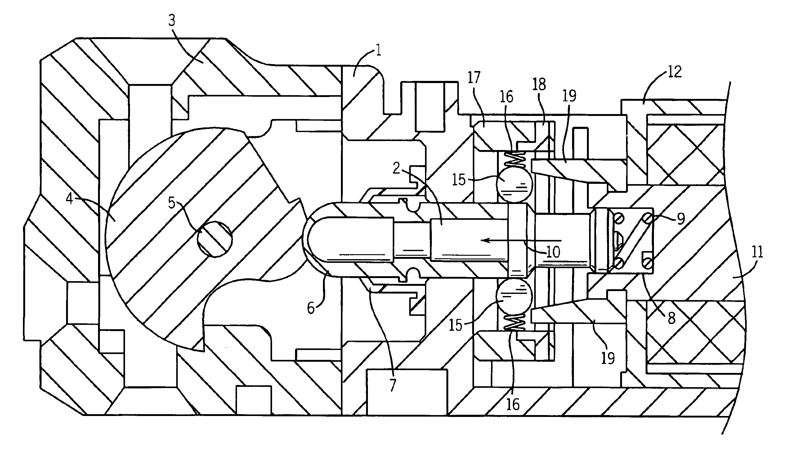
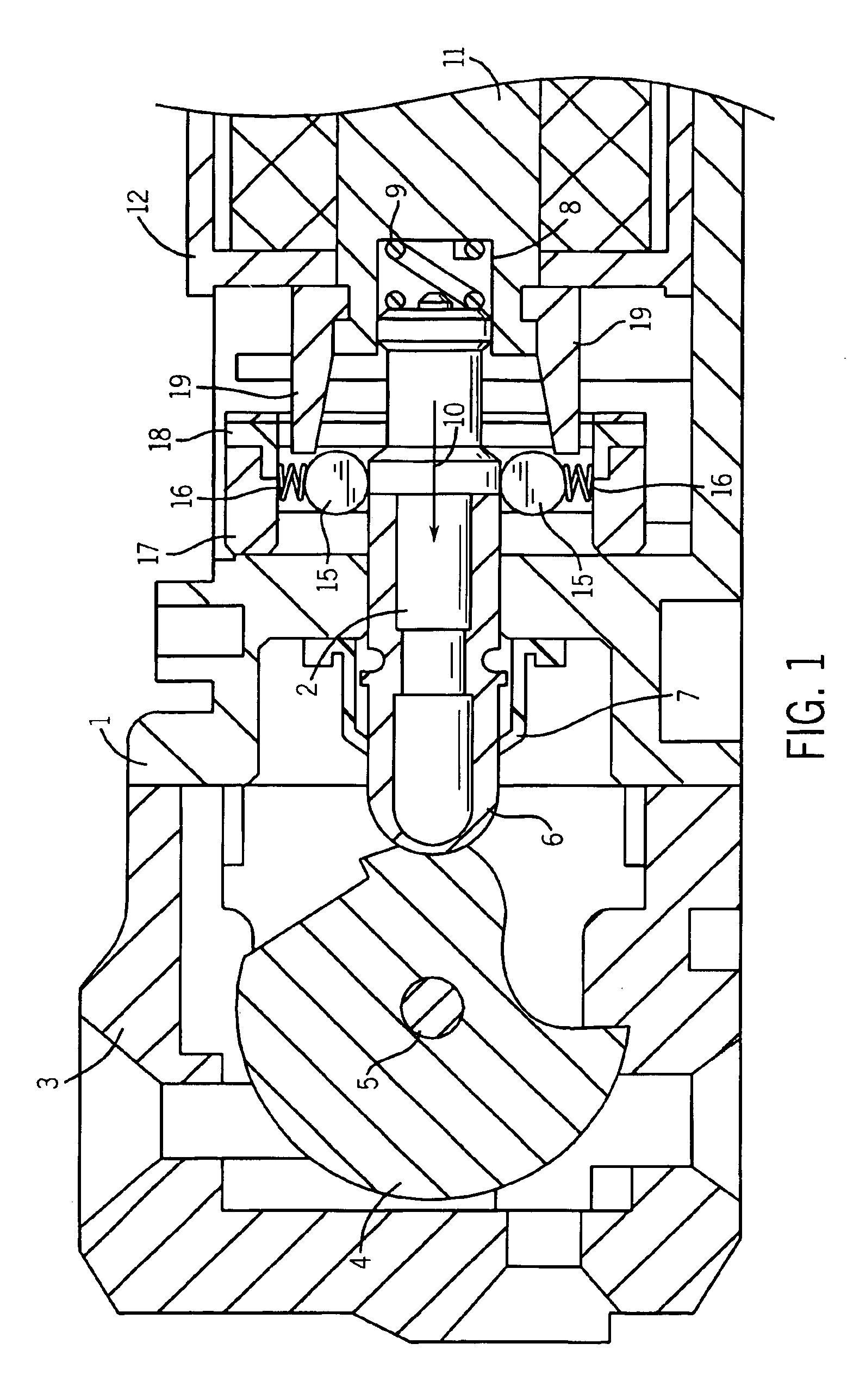
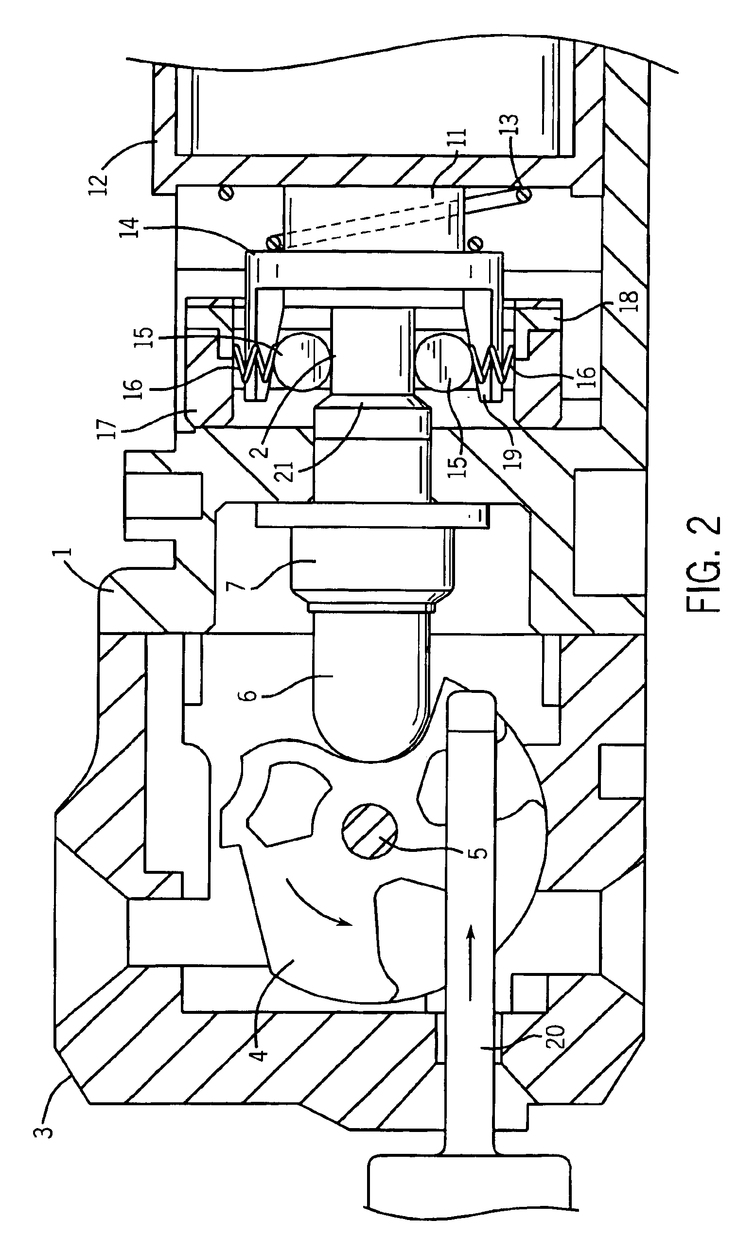
Referring to FIG. 1, the illustrated lockable switch mechanism comprises a housing 1 in which a plunger 2 is slidable and which supports a head assembly 3 supporting a rotatable cam 4, the cam 4 being rotatable about a pin 5. The plunger 2 comprises a metal core supporting an outer casing 6 which is slidably received in a sealing cap 7. The plunger 2 is symmetrical about its longitudinal axis and is slidable relative to the housing 1 along that axis.

The end of the plunger 2 remote from the cam 4 is received in a bore 8, a compression spring 9 being located within the bore 8 so as to bias the plunger 2 in the direction indicated by arrow 10. The bore 8 is formed in the end of a solenoid plunger 11 which is received within a solenoid housing 12. Energisation of a solenoid winding (not shown) in the solenoid housing 12 drives the solenoid plunger 11 to the right in FIG. 1. Denergisation of the solenoid results in the solenoid plunger 11 being moved to the left in FIG. 1 by a compressio...


PUM


Abstract

A lockable switch mechanism for a machine guard includes a switch plunger and locking and switch mechanisms. The plunger moves, upon insertion of an actuator, between two positions to actuate the switch mechanism and is locked by the locking mechanism, which has one locking member biased against a surface of the plunger and another locking member that is displaceable between locked and released positions. The plunger has an annular shoulder that displaces the first locking member when the plunger is moved. The second locking member prevents displacement of the first locking member by the plunger to thereby prevent movement of the plunger. Thus removal of the actuator is prevented unless the second locking member has been moved to the unlocked position when the machine is in a safe condition.

Description

CROSS-REFERENCE TO RELATED APPLICATIONSThis application claims priority to United Kingdom appl. Ser. No. 0214205, filed on Jun. 19, 2002 and published as GB 0214205D DO on Jul. 31, 2002. Related applications are published as EP 1376632 A1, published on Jan. 2, 2004, and JP 2004022549 A, published on Jan. 22, 2004.STATEMENT OF FEDERALLY SPONSORED RESEARCH OR DEVELOPMENTNot applicable.BACKGROUND OF THE INVENTIONThe present invention relates to a lockable switch mechanism which may be used in for example a machine guard to prevent the opening of a door of the machine guard until predetermined conditions have been established.A lockable switch mechanism is described in U.S. Pat. No. 5,777,284, hereby incorporated by reference as though fully set forth herein. That mechanism comprises a switch plunger which is mounted in a housing and is displaceable relative to the housing along a predetermined axis between a first unlocked position and a second locked position. A locking mechanism is p...

Claims


Application Information

Patent Timeline
IPC IPC(8): H01H27/00H01H9/20
CPCH01H27/007H01H2027/005
Inventor MOHTASHAM, MEDI
Owner ROCKWELL AUTOMATION
Why Eureka
Try Eureka