Thermostatic mixing valve with arrangement to increase mixing effect

A mixing valve and constant temperature technology, which is applied in the direction of temperature control, temperature control, and instruments without auxiliary power supply, and can solve problems such as affecting work, instability, and reducing the maximum flow rate.

Inactive Publication Date: 2002-09-04
MASCO CORP
View PDF1 Cites 7 Cited by
  • Summary
  • Abstract
  • Description
  • Claims
  • Application Information

AI Technical Summary

Problems solved by technology

In addition, in order to achieve effective mixing, the gap must be narrow, which will reduce the maximum flow rate provided by the mixing device, which is not desirable.
Finally, the pressure drop due to the cold water flowing through the narrow gap creates a force that exerts a dynamic drag on the disc
This dynamic resistance acts on the bias spring in the thermostat system and affects its operation, possibly causing instability in certain situations

Method used


Image

  • Thermostatic mixing valve with arrangement to increase mixing effect
  • Thermostatic mixing valve with arrangement to increase mixing effect
  • Thermostatic mixing valve with arrangement to increase mixing effect

Examples


Embodiment Construction

[0026] Detailed description of the preferred embodiment

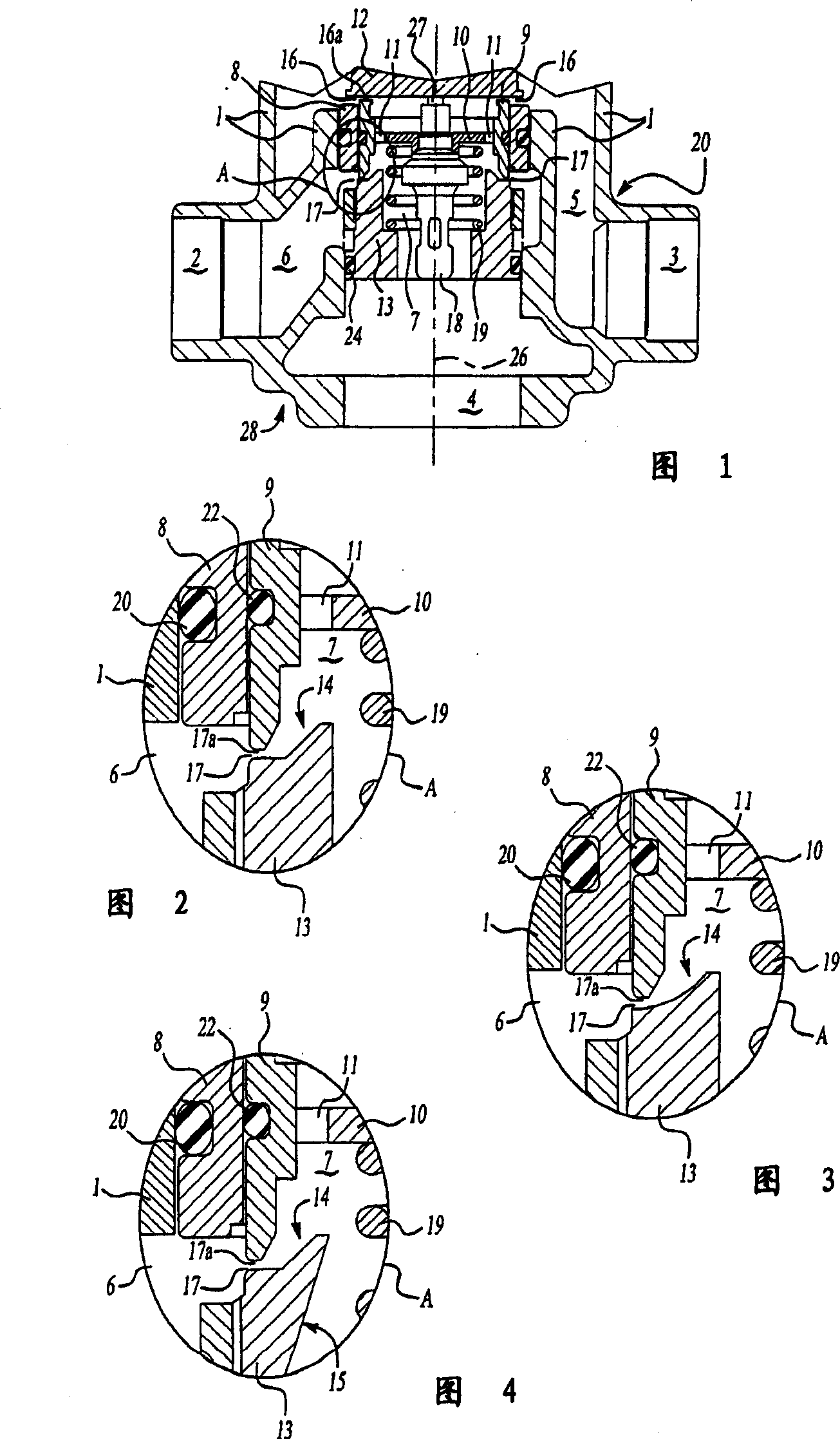
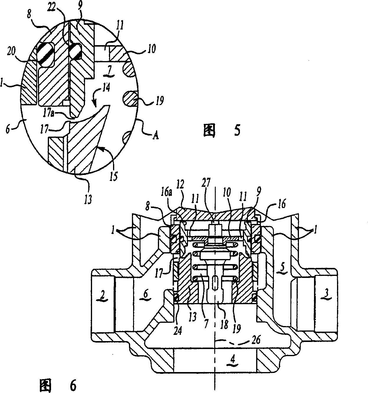
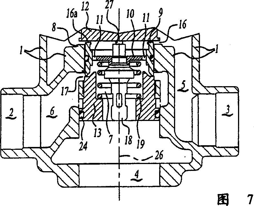
[0027] Referring now to FIG. 1, FIG. 1 is a partial sectional view of a thermostatic mixing valve introduced in an embodiment of the present invention. The operating handle and safety components of the thermostatic mixing valve and the parts for assembling the thermostatic mixing valve into the faucet located at the lower part of the thermostatic mixing valve are not shown, and these parts are not involved in the present invention. The thermostatic mixing valve comprises a valve body 1 with an inlet 2 for introducing hot water, an inlet 3 for introducing cold water and an outlet or discharge 4 for outputting mixed water at a regulated temperature. Connecting conduits 5 and 6 lead from the inlets 2 and 3 respectively to deliver cold and hot water to the mixing chamber 7 .

[0028] The mixing chamber 7 is delimited by an annular peripheral wall 8 . A valve 9 is slidably mounted in the peripheral wall 8 with a partition ...


PUM


Abstract

The invention relates to a thermostatic mixing valve, which comprises a valve body (1), inlets (2) and (3) for introducing hot water and cold water, and a discharge port (4) for discharging mixed water. The mixing chamber (7) is located in the valve body (1) and is defined by the surrounding wall (8), and the slide valve (9) is contained in the surrounding wall (8), and the slide valve (9) can slide in the mixing chamber to control and mix. Opening and closing of the entrance to the cavity (7). A thermostatic component (18) is installed to control the movement of the spool valve (9). A partition (10) is installed in the mixing chamber (7) between the inlets. The cross channel (11) allows water introduced from an inlet to flow through the partition to the outlet (4). The mixing chamber has an inclined surface (14), and the inclined surface (14) can introduce water flow from another inlet to the cross channel to improve the mixing effect of cold water and hot water.

Description

technical field [0001] The present invention relates to a thermostatic mixing valve, and more particularly to a structure within a thermostatic valve capable of improving the mixing effect of cold water and hot water supplied into a mixing chamber. Background of the invention [0002] The hot and cold water supplied to the thermostatic mixing valve must be mixed efficiently so that the thermostatic mixing valve can perform its thermostatic function in an optimal manner. The water must be thoroughly mixed before it comes into contact with the thermostatic components used to control the operation of the thermostatic valve. Thermostatic components typically consist of a wax-filled housing and a piston that moves under the thermal expansion of the contained wax. Therefore, many of the better quality thermostatic mixing valves incorporate structures that promote early and thorough mixing of the cold and hot water supplied to the mixing device before the mixed water comes into co...

Claims


Application Information

Patent Timeline
Patent Type & Authority Applications(China)
IPC IPC(8): G05D23/13
CPCG05D23/134
Inventor F·克纳普
Owner MASCO CORP
Why Eureka
Try Eureka