Connector

a technology of connecting rods and connecting rods, applied in the direction of connecting rods, electrical equipment, coupling devices, etc., can solve the problem that the moving plate cannot be returned to its original position, and achieve the effect of any damag

Active Publication Date: 2016-11-29
YAZAKI CORP
View PDF8 Cites 8 Cited by
  • Summary
  • Abstract
  • Description
  • Claims
  • Application Information

AI Technical Summary

Benefits of technology

[0029]According to the above configurations, the connector includes a male connector provided with a male connector body and a moving plate, and a female connector provided with a female connector body and a lever. In addition, the connector has a structure as follows. That is, a pair or a plurality of pairs of lock portions are formed in the female connector body. A pair or a plurality of pairs of plate lifting locks for engaging with the lock portions and releasing the engagement are formed in the moving plate. A plurality of lock deflection regulating portions for regulating deflection of the plate lifting locks are formed in the male connector body. Further, the plate lifting locks are formed so that different deflection can be made in accordance with their relative positions to the lock deflection regulating portions. When the connector configured thus is used, the moving plate can be lifted up at the time of connector release. Accordingly, the present disclosure has an advantage that the moving plate can be returned to its original position at the time of connector release.
[0030]Also, according to the above configurations, connector fitting can be performed even when the moving plate has sunk down to a deep position (the male terminal reception portion side) of the internal space of the hood portion. That is, even in the state where the lock deflection regulating portions have been disposed adjacently to the plate lifting locks of the moving plate that has sunk down, the plate lifting locks can be deflected not outward but in a falling-over direction so that the plate lifting locks and the lock portions will be able to be engaged with each other without any damage. Accordingly, when the connector according to the present disclosure is used, there is an advantage that connector fitting can be performed without any damage even when the moving plate has sunk down.

Problems solved by technology

That is, in the background art, there is a problem that the moving plate cannot be returned to its original position after connector fitting has been once performed.

Method used


Image

  • Connector
  • Connector
  • Connector

Examples


embodiment

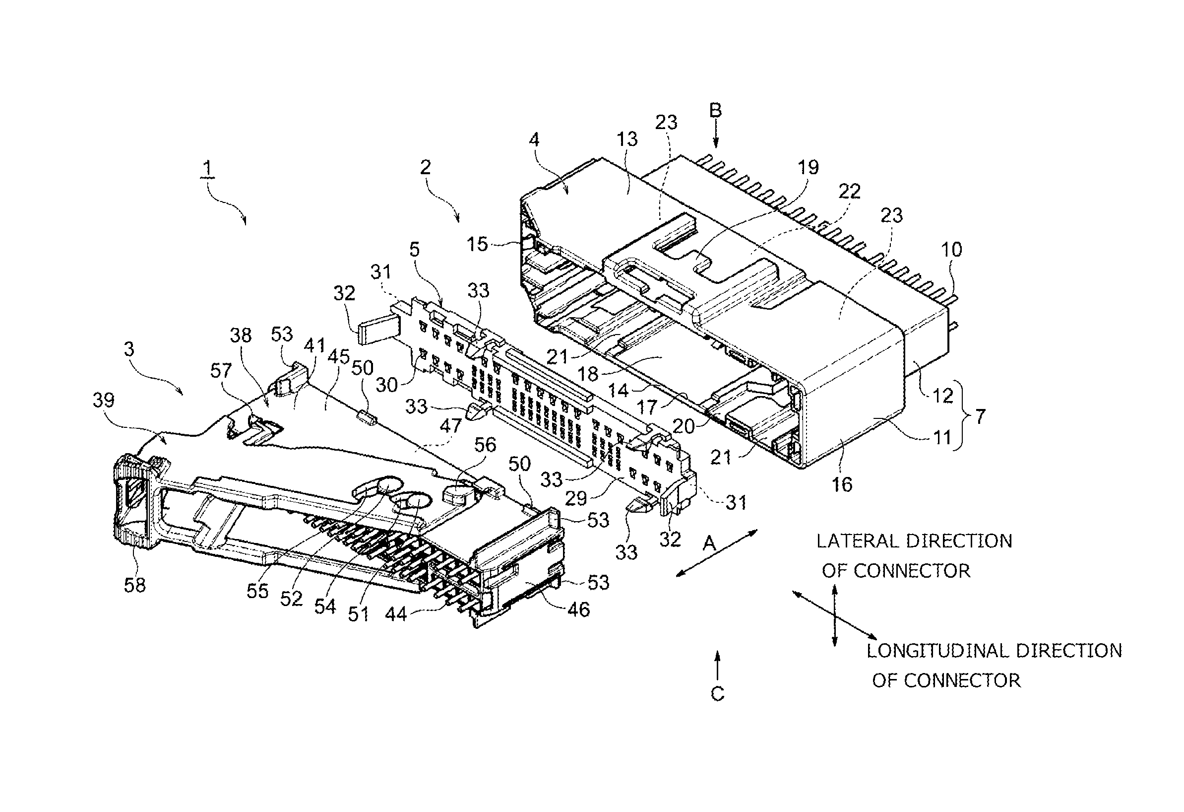
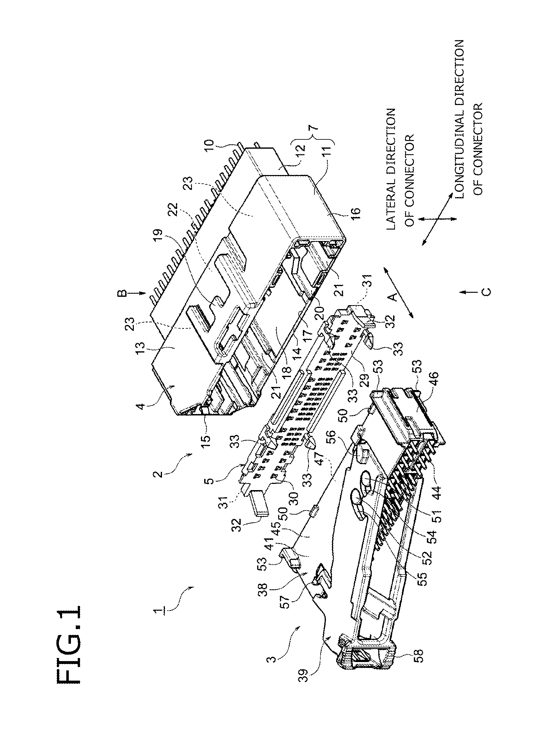
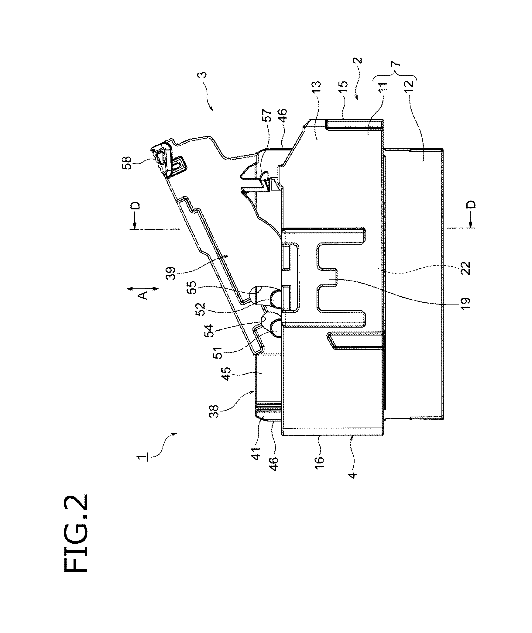
[0052]An embodiment will be described below with reference to the drawings. FIG. 1 is an exploded perspective view showing the configuration of the connector according to the present disclosure. FIG. 2 is a view showing a state of the connector immediately after the start of connector fitting. FIG. 2 is a view (in which electric wires are not shown) of the connector observed from the arrow B in FIG. 1. FIG. 3 is a sectional view taken on line D-D in FIG. 2. FIG. 4 is a perspective view of the moving plate.

[0053]FIG. 5 is a view (which includes a section and in which the electric wires, terminals and a lever are not shown) of the connector observed from the arrow C in FIG. 1, showing a state of the connector immediately after the start of connector fitting. FIG. 6 is a sectional view taken on line E-E in FIG. 5. FIG. 7 is a plan view showing a state of the plate lifting locks and the lock portions in FIG. 5 and FIG. 6.

[0054]In FIG. 1, a connector 1 is, for example, used in a cowl sid...


PUM


Abstract

When a female connector body is inserted into a hood portion in a temporary lock state of a moving plate, plate lifting locks are deflected in a falling-over direction which is different from an outside direction of a male connector housing by lock portions and the plate lifting locks and the lock portions are engaged with each other after the plate lifting locks are deflected in the falling-over direction.

Description

CROSS REFERENCE TO RELATED APPLICATIONS[0001]This application is based on Japanese Patent Application No. 2014-169317 filed on Aug. 22, 2014, the contents of which are incorporated herein by reference.BACKGROUND OF THE INVENTION[0002]1.Field of the Invention[0003]The present disclosure relates to a connector provided with a moving plate for positioning and protecting male type electric contact portions of male terminals.[0004]2. Description of the Related Art[0005]A connector to be used for electric connection includes a male connector and a female connector. The male connector is provided at an end part of one electric wire bundle while the female connector is provided at an end part of the other electric wire bundle. The male connector includes a male connector housing and a large number of male terminals. The male connector housing has a hood portion and a male terminal reception portion. The male terminals are received in the connector housing. When there are a large number of m...

Claims


Application Information

Patent Timeline
Patent Type & Authority Patents(United States)
IPC IPC(8): H01R13/627H01R13/629H01R13/631
CPCH01R13/631H01R13/627H01R13/62938
Inventor SHIMIZU, TOMOHIKO
Owner YAZAKI CORP
Why Eureka
Try Eureka