Electromagnetic linear valve

a linear valve and electric motor technology, applied in the direction of valve details, valve housings, valve arrangements, etc., can solve the problems of unstable structure and difficulty in coiling up the coil, and achieve the effect of avoiding the damage of other components caused by rotating a bolt in the assembling process and stable coil structur

Active Publication Date: 2015-06-30
XIAMEN KOGE MICRO TECH
View PDF18 Cites 4 Cited by
  • Summary
  • Abstract
  • Description
  • Claims
  • Application Information

AI Technical Summary

Benefits of technology

[0011]According to the description of the present invention, the beneficial effects from the technical scheme compared with the prior art are: firstly, the upper valve body and the lower valve of the present invention are connected by ultrasonic welding so that the connection is tight, stable and long working, and the damage of other components caused by rotating a bolt in the assembling process is avoided; secondly, the coil of the electromagnetic unit enwinds the corbelled trunk bulkhead so that it can coil up the coil around the corbelled trunk bulkhead instead of coiling up the coil in advance, so that the structure of the coil is more stable; thirdly, the controller board is set beneath the steel casing so that the integral structure of the electromagnetic linear valve is more compact and smaller.

Problems solved by technology

The main defects of the existing electromagnetic linear valve are: first of all, the two parts of the valve body are closured by bolts, being uneasy to assemble, and the movement of the bolts is easy to generate mismatch error or to damage related components; secondly, there is no support device for the coil of the electromagnetic unit so that it is not easy to coil up the coil and the structure is unstable; thirdly, the controller board of the electromagnetic unit is set beside the coil so that the volume of the valve body is big.

Method used


Image

  • Electromagnetic linear valve
  • Electromagnetic linear valve
  • Electromagnetic linear valve

Examples


Embodiment Construction

[0014]With the following description of the drawings, the specific embodiment of the present invention shall be further described in details.

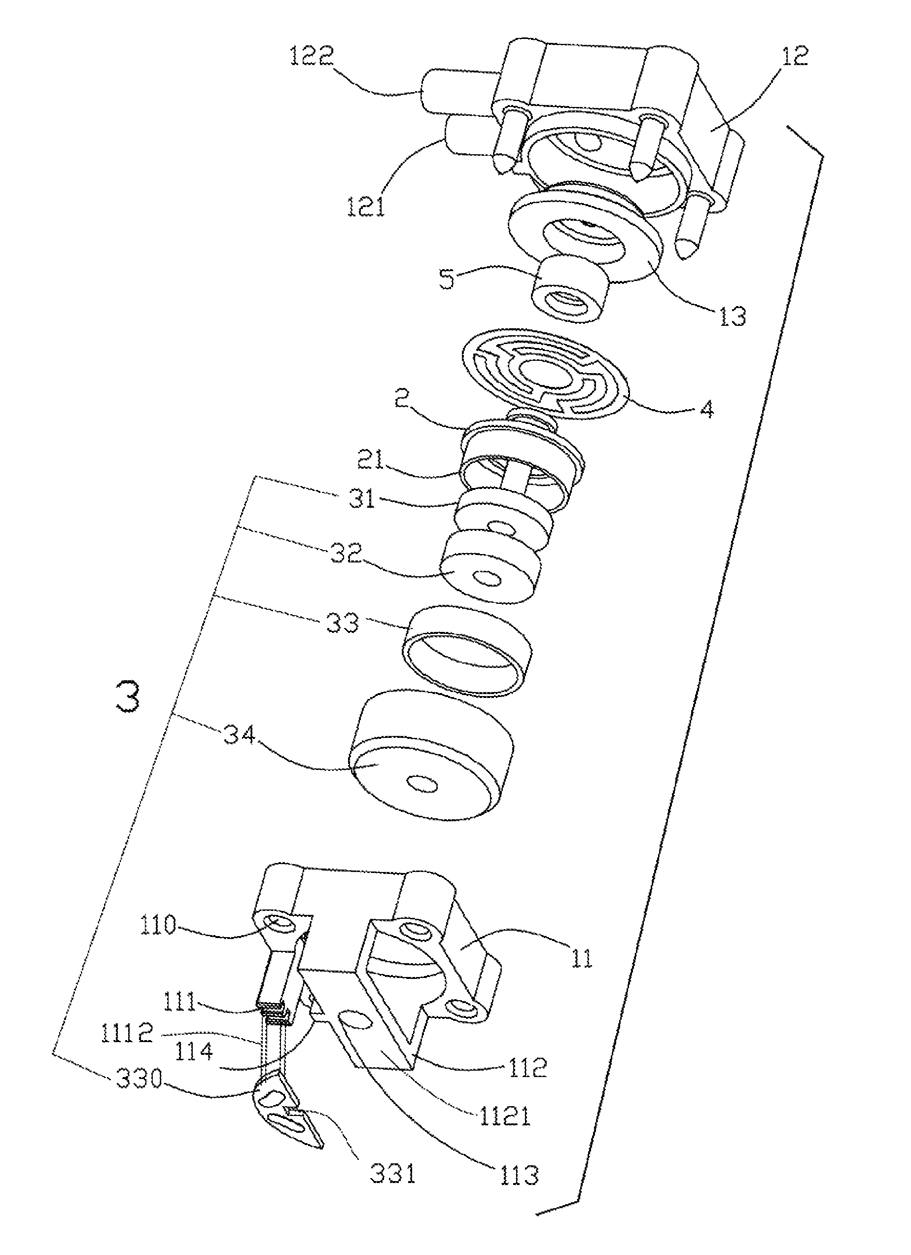
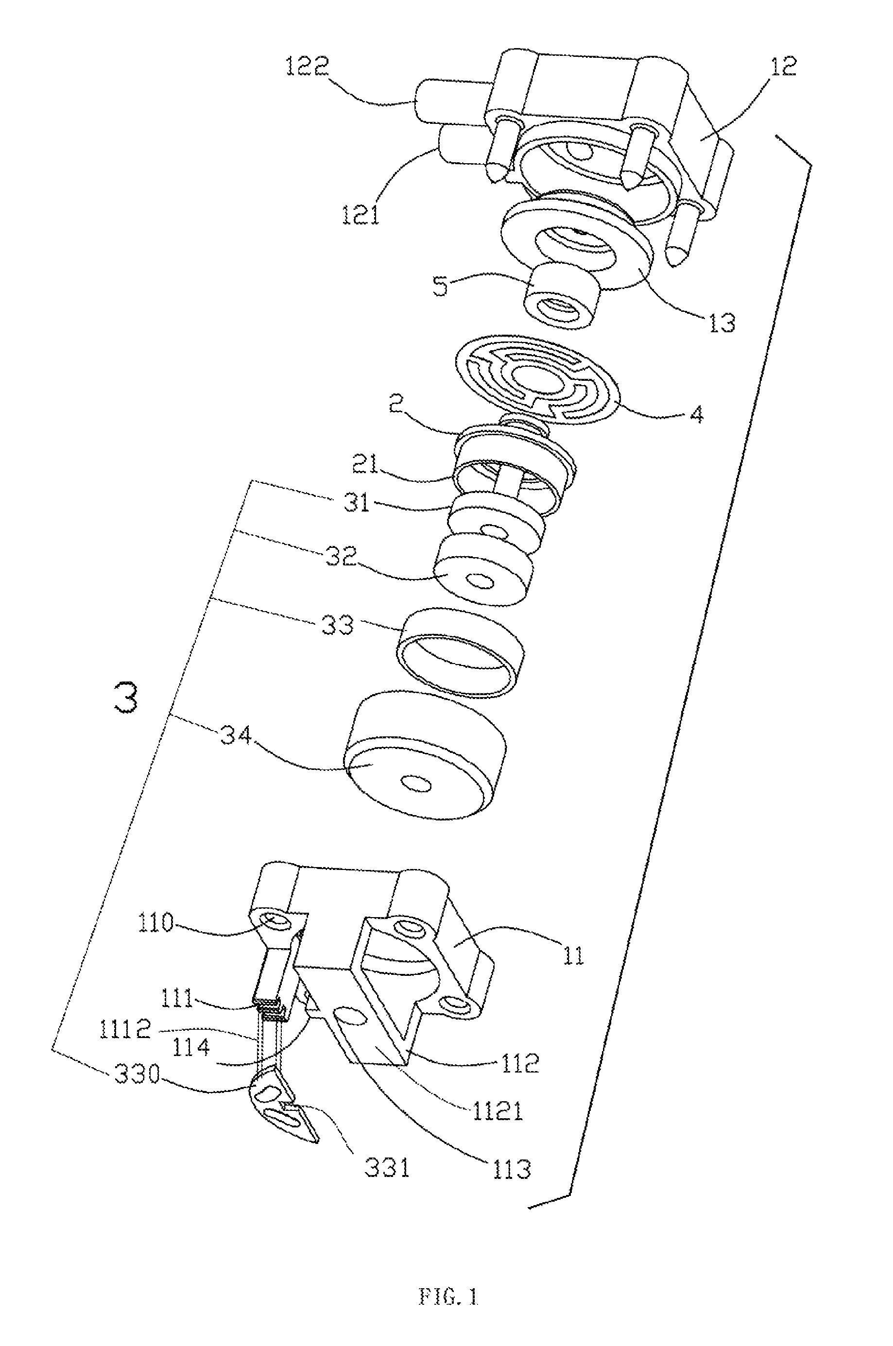
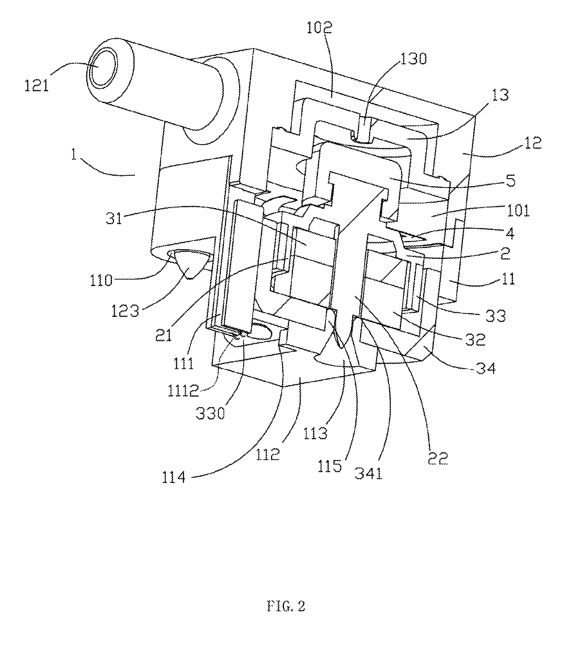
[0015]In FIG. 1 and FIG. 2, the electromagnetic linear valve of the present embodiments comprises a valve body 1 (which may also be referred to a as a “main valve body”), a movable element 2, an electromagnetic unit 3 driving the movable element 2 in the valve body 1 and a spring leaf 4.

[0016]The valve body 1 comprises a lower valve body 11 and a upper valve body 12, and each of the four corners of the upper valve body's 12 bottom surface has a concave pillar 123 projecting downward, and each of the four corners of the lower valve body 11 has a through hole 110 interacting with the concave pillar 123; the bottoms of the concave pillars 123 and of the through holes 110 are merged by ultrasonic welding, and each of the abutted surface belonging to the upper valve body 12 and the lower valve body 11 has stair-stepping face interacting with each ot...


PUM


Abstract

Provided is an electromagnetic linear valve that includes a main valve body having an upper valve body and a lower valve body. The upper valve body and the lower valve body are connected together by ultrasonic welding. The lower valve body comprises a frame. The electromagnetic linear valve includes a spring leaf and a movable element. An electromagnetic unit drives the movable element in the valve body, and the electromagnetic unit includes a steel casing that is fixed to the frame. A baffle divides the valve body into upper and lower valve chambers. The upper valve chamber has an inlet vent and an outlet vent. A through hole is formed in the baffle to connect the upper and lower valve chambers. The movable element has a valve plug blocking the through hole on the baffle.

Description

FIELD OF THE INVENTION[0001]The present invention relates to an electromagnetic linear valve that controls the switching of gas, more particularly to an electromagnetic linear valve with improved structure.BACKGROUND OF THE INVENTION[0002]The electromagnetic linear valve is widely used to control the switching of gas in the pipeline, and it mainly comprises a valve body, a movable element, an electromagnetic unit and a spring leaf. The valve body is divided into two valve chambers by a baffle having a through hole connecting the two valve chambers, and two valve chambers have an air inlet vent and an exhaust vent, and the movable element has a valve plug blocking the through hole on the baffle; the electromagnetic unit works together with the spring leaf to move the movable element and the valve plug and to make the valve plug switch between plugging the through hole and leaving the through hole.[0003]The main defects of the existing electromagnetic linear valve are: first of all, t...

Claims


Application Information

Patent Timeline
Patent Type & Authority Patents(United States)
IPC IPC(8): F16K31/02F16K31/06F16K27/10
CPCF16K27/102F16K31/0655
Inventor ZHANG, KUNLIN
Owner XIAMEN KOGE MICRO TECH
Why Eureka
Try Eureka