Card reader

a card reader and card reader technology, applied in the field of card readers, can solve problems such as difficulty in meeting energy saving needs, and achieve the effects of preventing damage to the solenoid, preventing excessive stress, and preventing damage to the pulling-preventing member

Active Publication Date: 2011-05-26
SANKYO SEIKI MFG CO LTD
View PDF3 Cites 5 Cited by
  • Summary
  • Abstract
  • Description
  • Claims
  • Application Information

AI Technical Summary

Benefits of technology

[0010]In at least an embodiment of the present invention, the card reader may be equipped with a support member on which the turning-regulating member abuts in the direction of the turning of the pulling-preventing member toward the open position, and also which supports the turning-regulating member. With this configuration, even if a user attempts to pull out the card while the turning of the pulling-preventing member in the closed position is regulated by the turning-regulating member, the force transmitted from the pulling-preventing member to the turning-regulating member is prevented from being transmitted further to the solenoid because of the work of the support member. Therefore, damage to the solenoid can be prevented.
[0011]In at least an embodiment of the present invention, the pulling-preventing member may be configured to be capable of turning about an axis in the width direction of the card, the width direction orthogonally intersecting with the card moving direction and the card thickness direction. With this configuration, even when the pulling-preventing member is urged to the closed position by the urging member, the pulling-preventing member can easily be turned to the open position by the inserted card.
[0012]In at least an embodiment of the present invention, the card reader may be equipped with a guide groove for guiding the turning-regulating member along the card moving direction and the solenoid be positioned such that the plunger moves in the card moving direction, the plunger constituting the solenoid and having the turning-regulating member fixed thereon. With this configuration, the turning-regulating member can be smoothly moved between the turning-regulating position and the turning position.
[0013]In at least an embodiment of the present invention, the pulling-preventing member may be provided with the turning center portion which is the center of turning of the pulling-preventing member, a card-abutting portion which abuts on the surface of the end portion of the card to prevent the card from being pulled out, and the regulating member abutting portion on which the turning-regulating member abuts, and the card abutting portion, the turning center portion and the regulating member abutting portion be arranged in this order along the card moving direction. With this configuration, even when the turning-regulating member abuts on the regulating member abutting portion and the turning of the pulling-preventing member is regulated, the card can be pulled out by flexing the portion between the turning center portion and the card abutting portion. Therefore, even if a user attempts to pull out the card while the turning-regulating member is abutting on the regulating member abutting portion to regulate the turning of the pulling-preventing member, an excessive stress is prevented from being applied to the pulling-preventing member and the turning-regulating member, thus preventing damage to the pulling-preventing member and the turning-regulating member.
[0014]In at least an embodiment of the present invention, the card reader may be equipped with a sensor for detecting the insertion of a card and the pulling-preventing member be provided with an insertion-detecting portion which collaborate with the sensor to detect the insertion of the card. With this configuration, part of the card-insertion detecting function can be given to the pulling-prevention member; therefore, there is no need to separately provide a member that would collaborate with the sensor to detect the card insertion. Thus, the configuration of the card reader can be simplified.
[0015]As described above, in a card reader having a card pulling-preventing function, the present invention can achieve energy savings.

Problems solved by technology

For this reason, more current needs to be applied to the solenoid during its operation, making it difficult to meet the energy saving needs.

Method used


Image

  • Card reader
  • Card reader
  • Card reader

Examples


Embodiment Construction

[0026]Embodiments of the present invention are described hereinafter based on the drawings.

(Configuration of Card Reader)

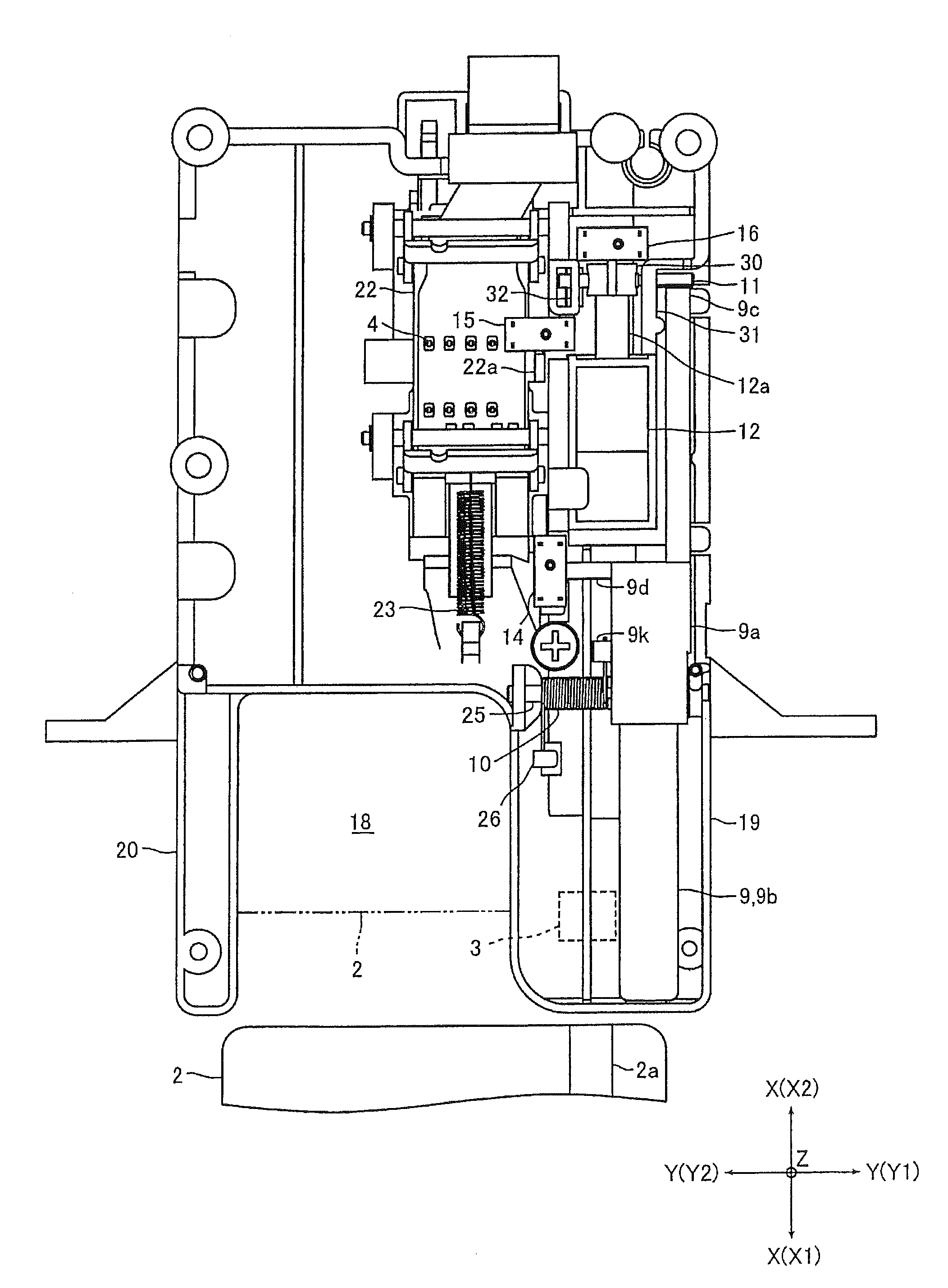
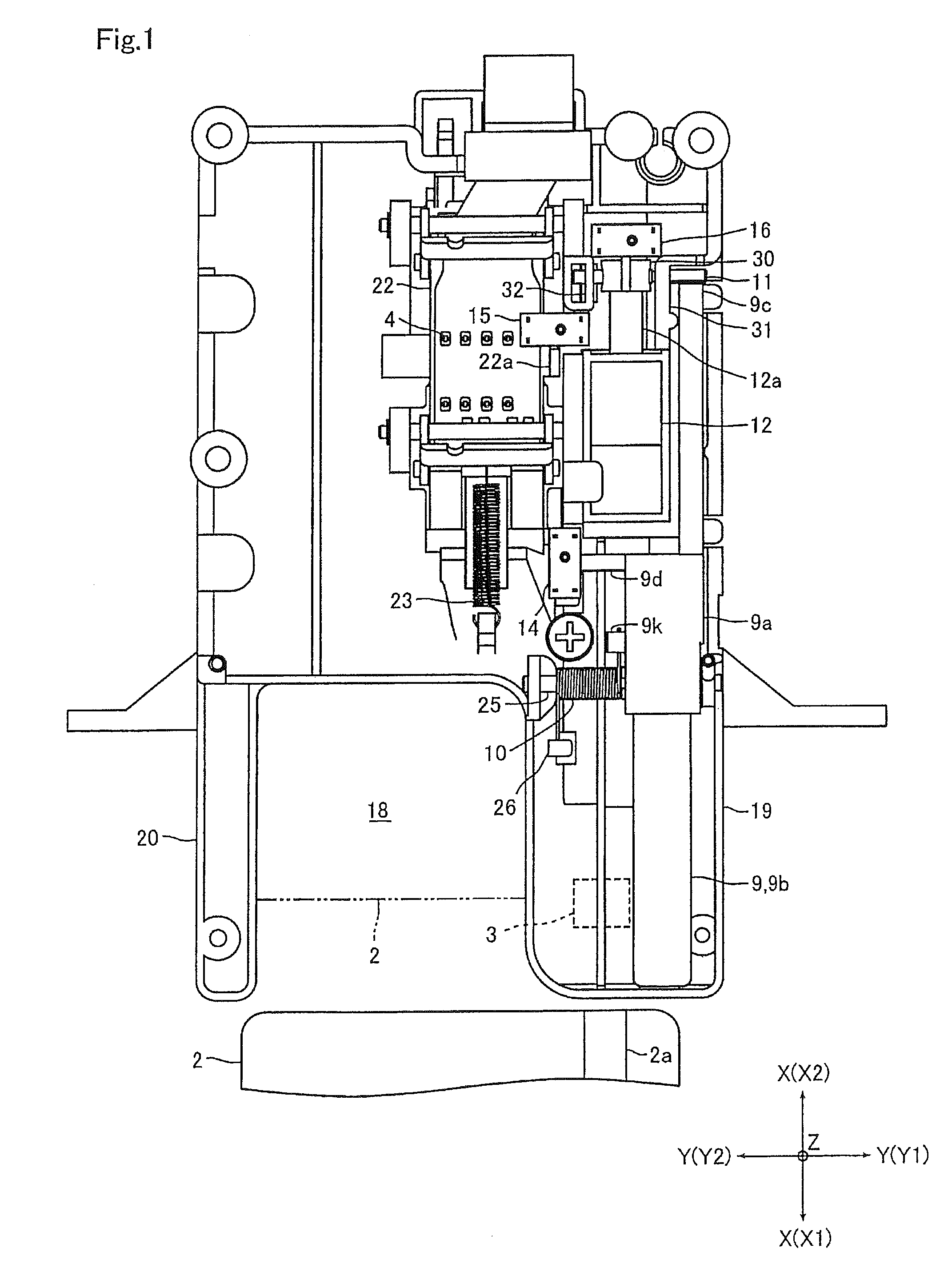
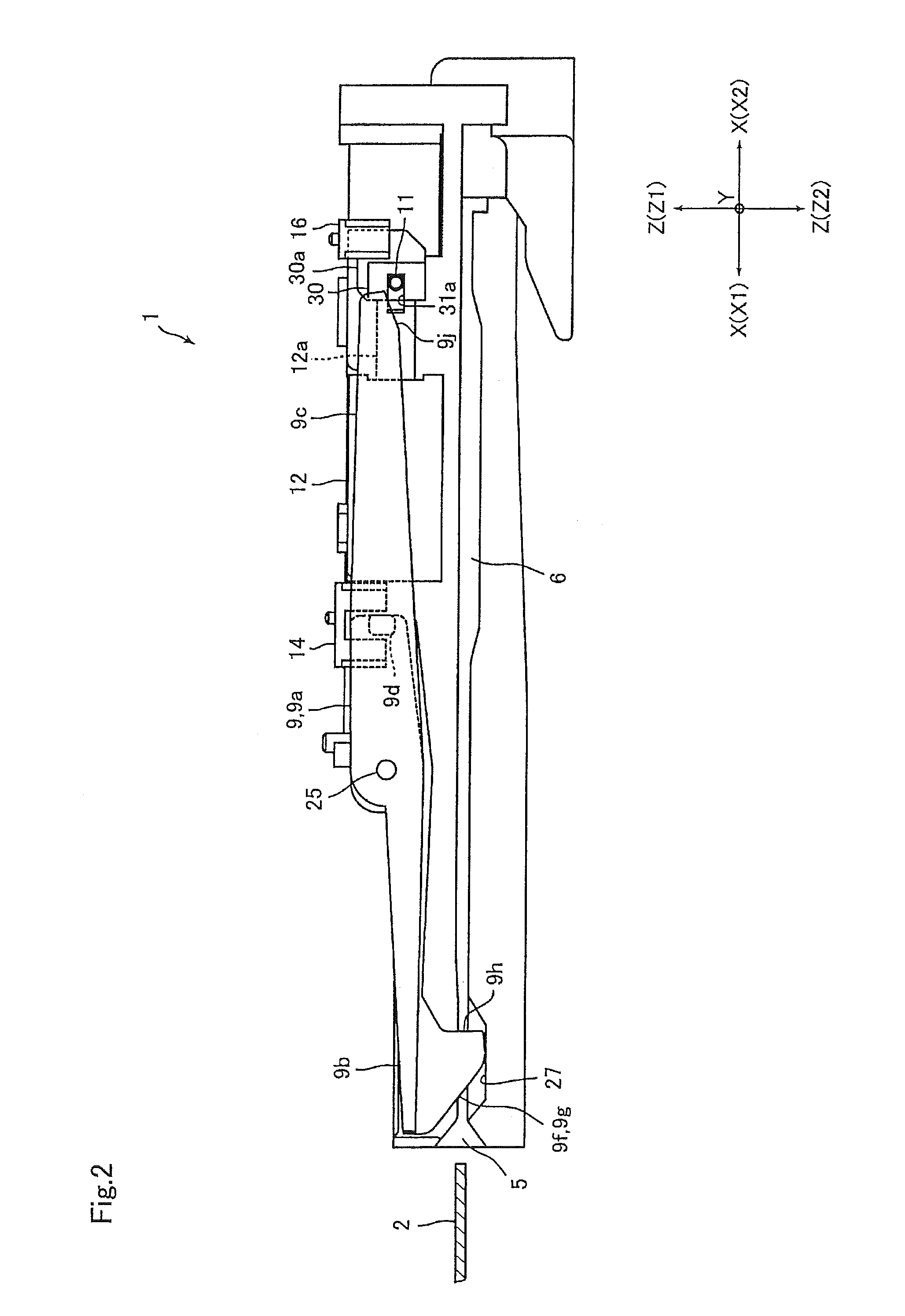
[0027]FIG. 1 is a plan view of a card reader 1 of an embodiment of the present invention. FIG. 2 is a diagram to explain the configuration of the card reader 1 shown in FIG. 1 from the side.

[0028]The card reader 1 of this embodiment is a device at which a user operates a card 2 by hand and which reproduces information recorded on the card 2 and records information on the card 2. The card reader 1, as shown in FIG. 1, is equipped with both a magnetic head 3 and IC contacts 4 for reproducing information recorded on the card 2 and recording information on the card 2. Inside the card reader 1, as shown in FIG. 2, a card moving passage 6 is formed linearly along which the card 2 inserted from a card insertion slot 2 moves.

[0029]The card reader 1 is also equipped with a lever member 9 which is a pulling-preventing member for preventing the card 2 inserted to the back fr...


PUM


Abstract

In a card reader having a card pulling-preventing function, provided is a card reader that can achieve energy savings. More specifically, a card reader 1 is equipped with a card moving passage 6 in which a card is moved, a pulling-preventing member 9 which is configured to be capable of turning to a closed position to close the card moving passage 6 and to an open position to open the card moving passage 6 and which prevents the pulling of the card at the closed position, an urging member 10 for urging the pulling-preventing member 9 to the closed position, a turning-regulating member which regulates the turning of the pulling-preventing member 9 by abutting on the pulling-preventing member 9 at the closed position, and a solenoid 12 which moves the turning-regulating member 11 to a turning-regulating position at which the turning of the pulling-preventing member 9 is regulated and to a turning position at which the turning of the pulling-preventing member 9 is enabled.

Description

CROSS REFERENCE TO RELATED APPLICATIONS[0001]This is a U.S. national stage of application No. PCT / JP2009 / 003325, filed on Jul. 15, 2009. Priority under 35 U.S.C. §119(a) and 35 U.S.C. §365(b) is claimed from Japanese Application No. 2008-188053, filed Jul. 22, 2008, the disclosure of which is also incorporated herein by reference.FIELD OF TECHNOLOGY[0002]The present invention relates to a card reader having a card pulling-preventing function that prevents inserted cards from being pulled out prematurely.BACKGROUND OF TECHNOLOGY[0003]Conventionally, widely-used are card readers having a card pulling-preventing function that prevents a card inserted to the back from being pulled out prematurely. A known example of this kind of card reader is one having a card locking member to lock the inserted card and a solenoid to drive the card locking member (see Patent reference 1, for example).[0004]In a card reader disclosed in Patent reference 1, the card locking member is provided with a sup...

Claims


Application Information

Patent Timeline
Patent Type & Authority Applications(United States)
IPC IPC(8): G06K7/01
CPCG06K13/08G06K13/0875G06K13/085
Inventor WATANABE, TAKEKITATAI, TOSHIO
Owner SANKYO SEIKI MFG CO LTD
Why Eureka
Try Eureka