Vehicle control system and vehicle control method

a technology of vehicle control system and vehicle control method, which is applied in the direction of vehicle position/course/altitude control, process and machine control, instruments, etc., can solve the problems of increasing the amount of processing time required to measure the positions of all the interfering objects, increasing the number of interfering objects, and increasing the amount of time between

Active Publication Date: 2017-01-10
DAIFUKU CO LTD
View PDF12 Cites 12 Cited by
  • Summary
  • Abstract
  • Description
  • Claims
  • Application Information

AI Technical Summary

Benefits of technology

[0007]To this end, a vehicle control system is desired in which an interference between a vehicle and interfering objects can be avoided as much as possible even when there is a large number of interfering objects within the measurement target area.
[0031]With the arrangement described above, it becomes possible to properly avoid any interference between the vehicle and a movable body even when a difference, or discrepancy, occurs between the managed position information for the wireless tags and the actual positions of the wireless tags due to the movements of the interfering objects, because the congested area travel mode is selected as the travel mode when the vehicle is about to be caused to travel in the section area that is determined to be in the congested state.

Problems solved by technology

However, with these position measurement portions, the amount of processing time required to measure the positions of all the interfering objects tends to increase with an increase in the number of the interfering objects; thus, there is a possibility that, for a given interfering object, the amount of time between the time the last position measurement was performed and the time a subsequent position measurement is performed (measurement cycle time) may be increased.
For this reason, there was a possibility that the difference between the measurement position and the actual position may become large as the measurement cycle time increases as described above; and there was a possibility that the position of each of the vehicle and the interfering objects cannot be properly managed.
And when the vehicle is caused to travel in such state, the vehicle or an interfering object may be located in an unexpected location, which leads to a possibility that an interference, or collision, between the vehicle and the interfering object may not be properly avoided.

Method used


Image

  • Vehicle control system and vehicle control method
  • Vehicle control system and vehicle control method
  • Vehicle control system and vehicle control method

Examples


first embodiment

[0051]The first embodiment in accordance with the present invention is described next with reference to the drawings.

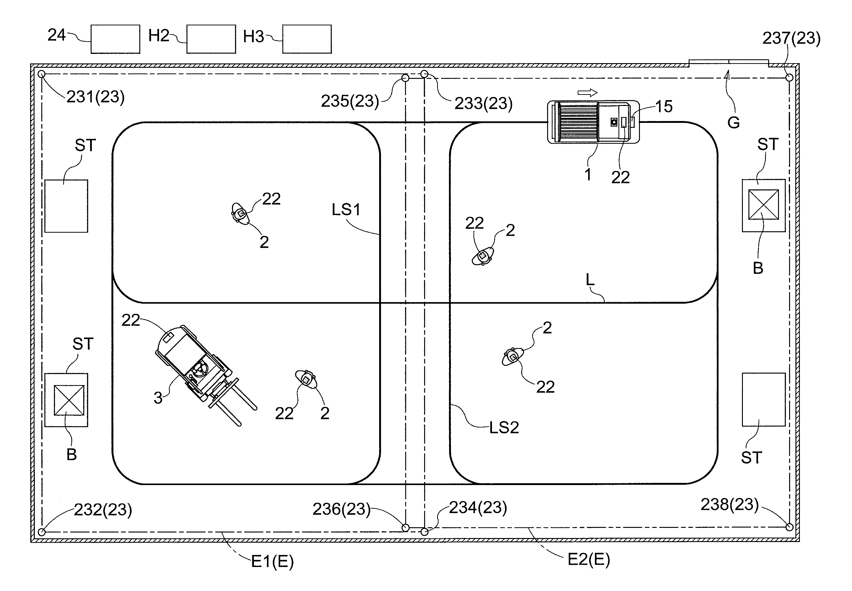
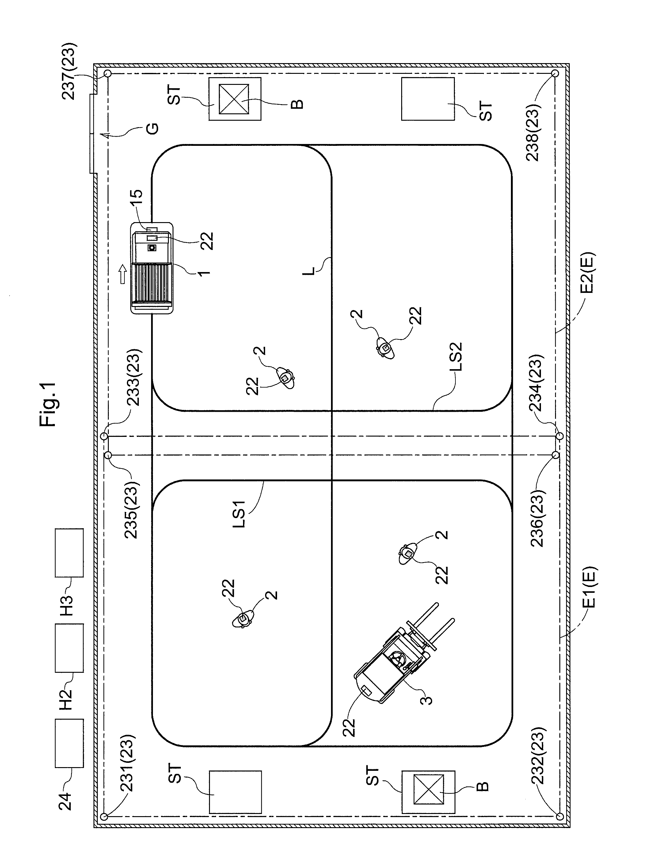
[0052]As shown in FIG. 1, an article transport facility includes a plurality of stations ST, each of which functions as an article transfer location provided at a side of the travel path L, and an article transport vehicle 1 configured to travel, or capable of traveling, on the floor and along the travel path L extending by way of, or along, the plurality of stations ST. And the article transport vehicle 1 travels autonomously along the travel path L to transport articles B (pallets as well as goods and things received and supported by the pallets in the present example) among the plurality of stations ST one article B at a time. In the present embodiment, the article transport vehicle 1 corresponds to the “vehicle” of the present invention.

[0053]In addition, in the article transport facility, workers 2 from outside walk on the floor and a fork lift truck 3, operated ...

second embodiment

[0119]Second embodiment of the present invention is described next. Since this second embodiment is different from the first embodiment only in the configuration of the section areas and the processes performed by the vehicle side controller H1, only the differences from the first embodiment are described, omitting the description of identical elements.

[0120]As shown in FIG. 10, the measurement target area E is divided into first section area E1 to 12th section area E12 in the second embodiment. Although the number of divided section areas is “12” in the present embodiment, this number is not limited to “12”, and can be any suitable number. In addition, to change the number of divided section areas, it is necessary to properly set the number of the base units 23 to be installed as well as the locations for installing these base units 23. More specifically, the base units 23 are arranged such that four base units 23 are associated with, and define, each section area and such that par...


PUM


Abstract

A position measurement portion manages a measurement target area by dividing the area into a plurality of section areas, and also manages, or keeps track of, an intra-area interfering object number which is the number of interfering objects in a given section area, independently for each of the plurality of the section areas. The travel controller determines, independently for each of the plurality of section areas, if the section area is in a congested state in which the intra-area interfering object number is greater than a set upper limit number, and selects a congested area travel mode as the travel mode when the travel controller is about to cause the vehicle to travel in a section area that is determined to be in the congested state.

Description

CROSS-REFERENCE TO RELATED APPLICATION[0001]This application claims priority to Japanese Patent Application No. 2013-088631 filed Apr. 19, 2013, the disclosure of which is hereby incorporated by reference in its entirety.FIELD OF THE INVENTION[0002]The present invention relates to a vehicle control system comprising a vehicle capable of traveling in a measurement target area, a travel controller which controls travel of the vehicle, and a position measurement portion which measures a position of the vehicle within the measurement target area and positions of a plurality of interfering objects within the measurement target area, wherein the travel controller is configured to control travel of the vehicle based on position information of the vehicle in the measurement target area and position information of the plurality of the interfering objects, measured by the position measurement portion. The present invention also relates to a vehicle control method that utilizes such vehicle co...

Claims


Application Information

Patent Timeline
Patent Type & Authority Patents(United States)
IPC IPC(8): G05D1/02
CPCG05D1/0223G05D1/0227G05D1/0244G05D1/0261G05D1/0272G05D1/0274G05D2201/0216
Inventor TSUJIMOTO, MASANORIHARA, YOSHIMASATAKAGAWA, NATSUOMARIYAMA, TOSHISADAKUBOTA, KOJI
Owner DAIFUKU CO LTD
Why Eureka
Try Eureka