Airbag device

a technology of airbags and supplemental bags, which is applied in the direction of vehicular safety arrangements, pedestrian/occupant safety arrangements, vehicle components, etc., can solve the problems of restricted inflation and deployment directions of supplemental bags, difficult to slide between mutual contact surfaces, and difficult to stably inflate and deploy supplemental bags

Active Publication Date: 2017-01-24
HONDA MOTOR CO LTD
View PDF12 Cites 16 Cited by
  • Summary
  • Abstract
  • Description
  • Claims
  • Application Information

AI Technical Summary

Benefits of technology

[0008]Thus, the present application is aimed at providing an airbag device that enables a main bag body of a main airbag unit to be stably inflated and deployed in a desired direction when impact is input.
[0010]According to the present application, when impact is input, the main bag body of the main airbag unit and the supplemental bag body of the supplemental airbag unit are inflated and deployed and the supplemental bag body comes into contact with the main bag body and thus, the main bag body is oriented in a desired direction and is stably inflated and deployed. As a result, an occupant can be stably supported by the main bag body.
[0019]In this case, when the main bag body and the supplemental bag body are inflated and deployed, each vent hole is prevented from being blocked by the opposite member that is in contact. Accordingly, the gas emission performances of the main bag body and the supplemental bag body can be stabilized.
[0023]In this case, when impact is input, the main bag body comes into contact with the supplemental bag body that completes the inflation and deployment earlier and thus, the restriction of the main bag body using the supplemental bag body is stabilized.

Problems solved by technology

However, as described above, if the bag body of the airbag device comes into contact with a peripheral member before completing the deployment, it is difficult for the bag body to be oriented in a desired direction and be stably inflated and deployed.
In this case, when impact is input, the inflated and deployed supplemental bag body comes into contact with the main bag body on the passenger seat side and the steering wheel on the driver seat side and thus, the inflation and deployment direction of the supplemental bag body is restricted.
In this case, when the main bag body is in contact with the supplemental bag body, it is difficult for the mutual contact surfaces to slide, and the inflation and deployment direction of the main bag body is stably restricted.

Method used


Image

  • Airbag device
  • Airbag device
  • Airbag device

Examples


first embodiment

[0037]A first embodiment illustrated in FIGS. 1 to 4 is described first.

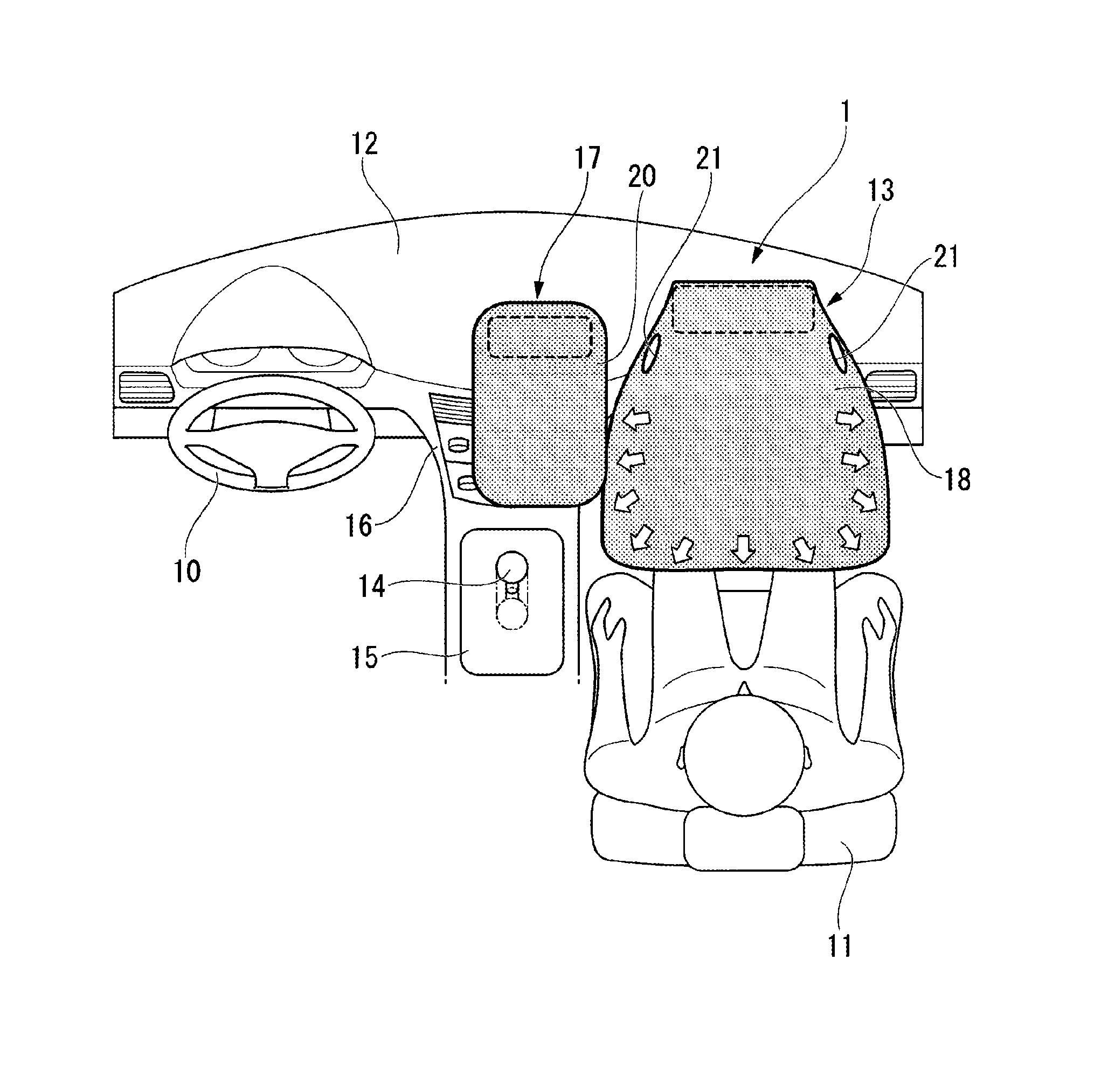
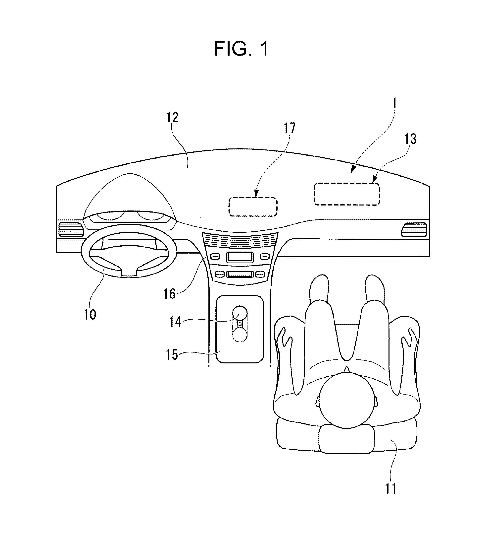
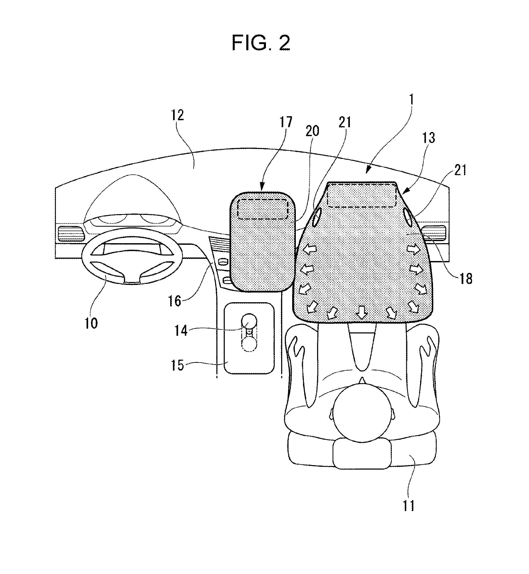
[0038]FIG. 1 illustrates the interior of a vehicle according to the first embodiment and FIGS. 2 to 4 illustrate a state in which an airbag device 1 in the interior of the vehicle in FIG. 1 is deployed.

[0039]The vehicle according to the present embodiment employs so-called left-hand drive, in which the driver seat is arranged on the left side of the vehicle interior and the passenger seat is arranged on the right side of the vehicle interior, and a steering wheel 10 is arranged on the left side of the vehicle interior. A main airbag unit 13 for the passenger seat is installed inside an instrument panel 12 in front of a seat 11, which is the passenger seat. Although the illustration and detailed description are omitted herein, a known airbag unit is installed in a central portion of the steering wheel 10 as well.

[0040]The instrument panel 12 is arranged across the front portion of the driver seat and the passenge...

second embodiment

[0058]According to the airbag device 101 of the second embodiment, when impact is input, the main bag body 118 comes into contact with a supplemental bag body 20 on the left side and the side panel 25 on the right side of the vehicle interior and is inflated and deployed while being sandwiched between the supplemental bag body 20 and the side panel 25.

[0059]Thus, according to the airbag device 101 of the present embodiment, the inflation and deployment direction of the main bag body 18 is restricted by the supplemental bag body 20 and the side panel 25 from both the right and left sides and thus, the main bag body 118 can be stably deployed in a more desirable direction.

[0060]FIGS. 7 to 10 illustrate a third embodiment. FIG. 7 illustrates the interior of a vehicle according to the third embodiment, and FIGS. 8 to 10 illustrate a state in which an airbag device 201 in the interior of the vehicle in FIG. 7 is deployed.

third embodiment

[0061]The airbag device 201 includes a main airbag unit 13 installed inside an instrument panel 12 in front of a seat 11, which is the passenger seat, a first supplemental airbag unit 217L installed in the instrument panel 12 and between a front position of the driver seat and a front position of the passenger seat, and a second supplemental airbag unit 217R installed in the instrument panel 12 and in a right side portion of the main airbag unit 13. The first supplemental airbag unit 217L includes a first supplemental bag body 220L that is inflated and deployed when impact is input, and the second supplemental airbag unit 217R includes a second supplemental bag body 220R that is inflated and deployed when impact is input. The first supplemental bag body 220L and the second supplemental bag body 220R break the top surface of the instrument panel 12 when impact is input, and change the respective orientations toward the rear side of the vehicle body to be inflated and deployed.

[0062]...


PUM


Abstract

An airbag device includes a main airbag unit with a main bag body that is inflated and deployed from a front side of a front seat when impact is input, and a supplemental airbag unit with a supplemental bag body that is inflated and deployed from a side portion of the main airbag unit when impact is input. The supplemental bag body comes into contact with the main bag body when inflated and deployed and restricts inflation and deployment of the main bag body.

Description

CROSS REFERENCES TO RELATED APPLICATIONS[0001]The present application claims priority under 35 U.S.C. §119 to Japanese Patent Application No. 2014-246795, filed Dec. 5, 2014, entitled “AIRBAG DEVICE.” The contents of this application are incorporated herein by reference in their entirety.BACKGROUND[0002]1. Field[0003]The present application relates to an airbag device that protects an occupant seated on a front seat of a vehicle.[0004]2. Description of the Related Art[0005]An airbag device with a bag body that is inflated and deployed to protect an occupant when impact is input is provided in front of the driver seat or the passenger seat of a vehicle. The airbag device is arranged inside a steering wheel or an instrument panel as an airbag unit including an inflator that generates high-pressure gas when impact is input and a bag body that is inflated and deployed on receiving the gas of the inflator (see, for example, Japanese Patent No. 5470222).[0006]A bag body of an airbag devic...

Claims


Application Information

Patent Timeline
Patent Type & Authority Patents(United States)
IPC IPC(8): B60R21/233B60R21/231B60R21/205B60R21/239B60R21/00
CPCB60R21/231B60R21/233B60R21/205B60R21/239B60R2021/0032B60R2021/23107
Inventor SATO, MASAHIROFUKUDA, KANICHIAMAKASU, YUICHI
Owner HONDA MOTOR CO LTD
Why Eureka
Try Eureka