Backlight module and display device
A backlight module, backlight technology, applied in optics, nonlinear optics, instruments, etc., can solve the problems of too small seam, too large seam, uneven size, etc., to achieve easy operation, improve performance stability, structure simple effect
- Summary
- Abstract
- Description
- Claims
- Application Information
AI Technical Summary
Problems solved by technology
Method used
Image
Examples
Embodiment 1
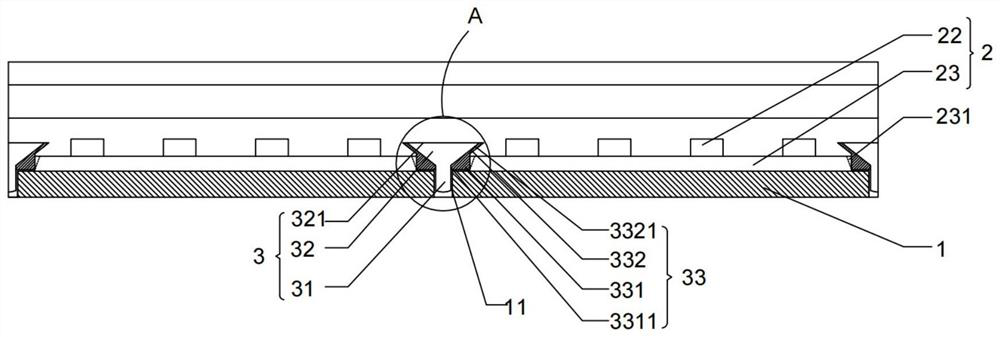
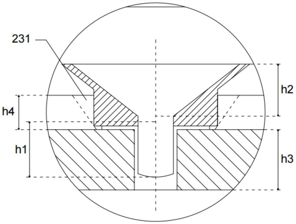
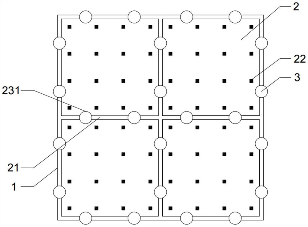
[0036] Please refer to Figure 1 to Figure 3 , the present invention provides a backlight module, comprising a backplane 1 and a plurality of backlight elements 2 mounted on the backplane 1; a plurality of the backlight elements 2 are arranged on the backplane 1, and two adjacent ones A seam 21 is spaced between the backlight parts 2; an adjustment part 3 is installed at each of the seam 21; the adjustment part 3 includes:
[0037] A connecting portion 31, one end of the connecting portion 31 is installed on the backboard 1 through the seam 21; the depth of the connecting portion 31 being installed into the backboard 1 is adjustable; and,
[0038] The adjusting portion 32 is disposed at one end of the connecting portion 31 away from the back plate 1 , and the outer diameter of the adjusting portion 32 tapers in the direction toward the back plate 1 ; one end of the adjusting portion 32 enters the The seam 21 is adjusted; the degree to which the adjusting part 32 enters the se...
Embodiment 2
[0080] refer to Figure 4 and Figure 5 , the backlight module includes a backplane 1 and a backlight element 2 mounted on the backplane 1; a plurality of the backlight elements 2 are mounted on the backplane 1, between two adjacent backlight elements 2 There are seams 21 at intervals; one or more adjustment members 3 are installed at each of the seams 21; the adjustment members 3 include:
[0081] A connecting portion 31, one end of the connecting portion 31 is installed on the backboard 1 through the seam 21; the depth of the connecting portion 31 being installed into the backboard 1 is adjustable; and,
[0082] The adjusting portion 32 is disposed at one end of the connecting portion 31 away from the back plate 1 , and the outer diameter of the adjusting portion 32 tapers in the direction toward the back plate 1 ; one end of the adjusting portion 32 enters the The seam 21 is adjusted; the width of the seam 21 is adjusted by adjusting the degree to which the adjusting port...
Embodiment 3
[0089] The present invention also provides a display device, refer to Image 6 , including: a casing 300, a backlight module 100 and a display panel 200;
[0090] The backlight module 100 is the backlight module described in Embodiment 1 or Embodiment 2, and is installed in the housing 300;
[0091] The display panel 200 is mounted on the casing 300 , and the display panel 200 is located on the light-emitting side of the backlight module 100 .
[0092] The backlight module 100 includes the backplane 1 and the backlight element 2 mounted on the backplane 1 ; the backlight element 2 includes a plurality of substrates 23 , and the substrates 23 are regularly arranged in phase. There is the seam 21 between two adjacent substrates 23 ; the seam 21 is installed with one or more adjustment members 3 ; the backlight 2 includes a substrate 23 and a substrate 23 mounted on the substrate 23 . The Mini LED light-emitting units 22 are mounted on the side of the substrate 23 away from the...
PUM
 Abstract
Description
Claims
Application Information
 - R&D
- Intellectual Property
- Life Sciences
- Materials
- Tech Scout
- Unparalleled Data Quality
- Higher Quality Content
- 60% Fewer Hallucinations
Browse by: Latest US Patents, China's latest patents, Technical Efficacy Thesaurus, Application Domain, Technology Topic, Popular Technical Reports.
© 2025 PatSnap. All rights reserved.Legal|Privacy policy|Modern Slavery Act Transparency Statement|Sitemap|About US| Contact US: help@patsnap.com


