
Modal change based on orientation of a portable multifunction device

a multi-functional device and orientation technology, applied in static indicating devices, instruments, substation equipment, etc., can solve the problems of preventing the configuration and/or adaptation of a user interface, inflexible user interfaces such as physical pushbuttons, and complicated key sequences and menu hierarchy

Active Publication Date: 2017-02-21
APPLE INC
View PDF198 Cites 3 Cited by
  • Summary
  • Abstract
  • Description
  • Claims
  • Application Information

AI Technical Summary

Benefits of technology

The invention is about creating portable devices that have more transparent and user-friendly interfaces. The goal is to make it easier for people to switch between different modes within a specific application.

Problems solved by technology

As portable electronic devices become more compact, and the number of functions performed by a given device increase, it has become a significant challenge to design a user interface that allows users to easily interact with a multifunction device.
This challenge is particular significant for handheld portable devices, which have much smaller screens than desktop or laptop computers.
This situation is unfortunate because the user interface is the gateway through which users receive not only content but also responses to user actions or behaviors, including user attempts to access a device's features, tools, and functions.
These conventional user interfaces often result in complicated key sequences and menu hierarchies that must be memorized by the user.
Many conventional user interfaces, such as those that include physical pushbuttons, are also inflexible.
This is unfortunate because it may prevent a user interface from being configured and / or adapted by either an application running on the portable device or by users.
When coupled with the time consuming requirement to memorize multiple key sequences and menu hierarchies, and the difficulty in activating a desired pushbutton, such inflexibility is frustrating to most users.

Method used


Image

  • Modal change based on orientation of a portable multifunction device
  • Modal change based on orientation of a portable multifunction device
  • Modal change based on orientation of a portable multifunction device

Examples


Embodiment Construction

[0024]Reference will now be made in detail to embodiments, examples of which are illustrated in the accompanying drawings. In the following detailed description, numerous specific details are set forth in order to provide a thorough understanding of the present invention. However, it will be apparent to one of ordinary skill in the art that the present invention may be practiced without these specific details. In other instances, well-known methods, procedures, components, circuits, and networks have not been described in detail so as not to unnecessarily obscure aspects of the embodiments.

[0025]It will also be understood that, although the terms first, second, etc. may be used herein to describe various elements, these elements should not be limited by these terms. These terms are only used to distinguish one element from another. For example, a first gesture could be termed a second gesture, and, similarly, a second gesture could be termed a first gesture, without departing from t...


PUM


Abstract

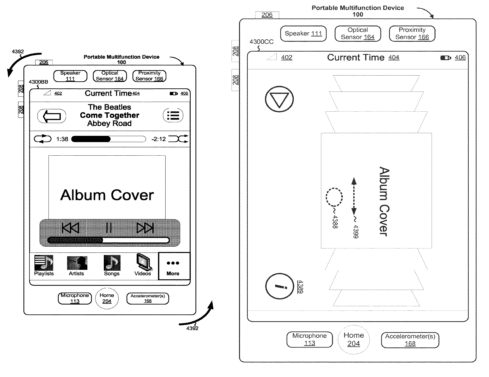
In accordance with some embodiments, a computer-implemented method is performed at a portable multifunction device with a rectangular touch screen display that includes a portrait view and a landscape view. The method includes detecting the device in a first orientation, and while the device is in the first orientation, displaying an application in a first mode on the touch screen display in a first view. The method also includes detecting the device in a second orientation, and in response to detecting the device in the second orientation, displaying the application in a second mode on the touch screen display in a second view. The first mode of the application differs from the second mode of the application by more than a change in display orientation.

Description

RELATED APPLICATIONS[0001]This application is a continuation of U.S. patent application Ser. No. 11 / 969,800, “Modal Change Based on Orientation of a Portable Multifunction Device,” filed Jan. 4, 2008, which claims priority to U.S. Provisional Patent Application No. 60 / 937,993, “Portable Multifunction Device,” filed Jun. 29, 2007; 60 / 947,300, “Modal Change Based on Orientation of a Portable Multifunction Device,” filed Jun. 29, 2007; 60 / 879,469, “Portable Multifunction Device,” filed Jan. 8, 2007; and 60 / 879,253, “Portable Multifunction Device,” filed Jan. 7, 2007. All of these applications are incorporated by reference herein in their entirety.[0002]This application is related to the following applications: (1) U.S. patent application Ser. No. 10 / 188,182, “Touch Pad For Handheld Device,” filed Jul. 1, 2002; (2) U.S. patent application Ser. No. 10 / 722,948, “Touch Pad For Handheld Device,” filed Nov. 25, 2003; (3) U.S. patent application Ser. No. 10 / 643,256, “Movable Touch Pad With Ad...

Claims


Application Information

Patent Timeline
Patent Type & Authority Patents(United States)
IPC IPC(8): G06F3/0487G06F1/16G06F3/0488G06F3/0484G06F3/041H04M1/725H04M1/72442
CPCG06F3/0487G06F1/1626G06F1/1656G06F1/1684G06F3/0412G06F3/04845G06F3/04883G06F2200/1614G06F2200/1637G09G2340/0492G09G2340/145G09G2354/00H04M1/72558H04M2250/12H04M2250/22H04M1/72442
Inventor FORSTALL, SCOTTPISULA, CHARLES J.CHAUDHRI, IMRANANZURES, FREDDY ALLENJOBS, STEVEN P.HERZ, SCOTT
Owner APPLE INC
Learn More